A curated collection of PCB and hardware projects crafted by our talented Flux community.
Though people use the terms "circuit diagram" and "schematic diagram" interchangeably, subtle differences exist between them. A circuit diagram leans more toward representing the physical aspects of an electrical circuit, indicating the layout and wiring connections. In contrast, a schematic diagram focuses on the function and logic behind each component, utilizing electrical symbols and electronic symbols to depict how they connect.

The resistor is a fundamental component that restricts current flow. Its symbol in a circuit diagram and schematic diagram is a jagged line. Understanding resistor placement and ratings is essential for controlling voltage and current in your circuit.

Capacitors store and discharge electrical energy. They are symbolized by two parallel lines in schematics and circuit diagrams. Incorrectly placing a capacitor can lead to ineffective signal filtering or energy storage.

An inductor symbol resembles a coiled line and is integral in applications like energy storage and signal filtering. Understanding inductors in a circuit diagram is crucial for radio-frequency circuits and power management.

These semiconductor devices can either amplify signals or act as a switch. Transistors consist of three terminals: the base, collector, and emitter. Depending on the type of transistor, its symbol varies slightly but is easily recognizable.
Logic gates are the bread and butter of digital circuits. They perform basic Boolean operations like AND, OR, and NOT. Different shapes represent these gates, allowing for rapid identification and understanding of the circuit's digital logic.
While hand-drawing circuit diagrams remains a valuable skill, software or web app like Flux or KiCad provides a more efficient, error-proof method for diagramming. These tools allow you to create intricate circuit and schematic diagrams, complete with every electrical symbol and electronic symbol you need. Moreover, these tools can generate a netlist, a text-based representation of the circuit that provides details about the connections between components, enabling seamless transitions from design to prototyping.
In both circuit and schematic diagrams, a netlist serves as a valuable asset. It is a textual depiction of the electrical circuit, listing every component and its connections. Engineers often generate netlists from software like KiCad, which then serves as input for simulations or as guidelines for physical circuit assembly.
A circuit diagram stands as a nexus between the theoretical framework and practical implementation of an electrical circuit. It is a tool for visual communication, using a well-defined set of electrical and electronic symbols to represent complex circuitry. Beyond merely a drawing, it serves as a functional map, especially when enhanced by software tools like KiCad and supplementary elements like netlists.
By grasping the basic components like resistors, capacitors, inductors, and transistors, along with more advanced elements like logic gates, engineers can navigate the complexities of electronic design. Thorough understanding enables one to transition from novice tinkerer to seasoned designer, proficient in creating both circuit diagrams and their more logic-focused counterparts, schematic diagrams.
Whether you're sketching your initial design or refining your final product, recognizing the nuances and best practices in diagramming can set you on the path to more effective, efficient, and innovative electronic creations.
Though people use the terms "circuit diagram" and "schematic diagram" interchangeably, subtle differences exist between them. A circuit diagram leans more toward representing the physical aspects of an electrical circuit, indicating the layout and wiring connections. In contrast, a schematic diagram focuses on the function and logic behind each component, utilizing electrical symbols and electronic symbols to depict how they connect.
The resistor is a fundamental component that restricts current flow. Its symbol in a circuit diagram and schematic diagram is a jagged line. Understanding resistor placement and ratings is essential for controlling voltage and current in your circuit.
Capacitors store and discharge electrical energy. They are symbolized by two parallel lines in schematics and circuit diagrams. Incorrectly placing a capacitor can lead to ineffective signal filtering or energy storage.
An inductor symbol resembles a coiled line and is integral in applications like energy storage and signal filtering. Understanding inductors in a circuit diagram is crucial for radio-frequency circuits and power management.
These semiconductor devices can either amplify signals or act as a switch. Transistors consist of three terminals: the base, collector, and emitter. Depending on the type of transistor, its symbol varies slightly but is easily recognizable.
Logic gates are the bread and butter of digital circuits. They perform basic Boolean operations like AND, OR, and NOT. Different shapes represent these gates, allowing for rapid identification and understanding of the circuit's digital logic.
While hand-drawing circuit diagrams remains a valuable skill, software or web app like Flux or KiCad provides a more efficient, error-proof method for diagramming. These tools allow you to create intricate circuit and schematic diagrams, complete with every electrical symbol and electronic symbol you need. Moreover, these tools can generate a netlist, a text-based representation of the circuit that provides details about the connections between components, enabling seamless transitions from design to prototyping.
In both circuit and schematic diagrams, a netlist serves as a valuable asset. It is a textual depiction of the electrical circuit, listing every component and its connections. Engineers often generate netlists from software like KiCad, which then serves as input for simulations or as guidelines for physical circuit assembly.
A circuit diagram stands as a nexus between the theoretical framework and practical implementation of an electrical circuit. It is a tool for visual communication, using a well-defined set of electrical and electronic symbols to represent complex circuitry. Beyond merely a drawing, it serves as a functional map, especially when enhanced by software tools like KiCad and supplementary elements like netlists.
By grasping the basic components like resistors, capacitors, inductors, and transistors, along with more advanced elements like logic gates, engineers can navigate the complexities of electronic design. Thorough understanding enables one to transition from novice tinkerer to seasoned designer, proficient in creating both circuit diagrams and their more logic-focused counterparts, schematic diagrams.
Whether you're sketching your initial design or refining your final product, recognizing the nuances and best practices in diagramming can set you on the path to more effective, efficient, and innovative electronic creations.


In this article, we will provide a comprehensive guide to the Raspberry Pi pinout diagram, including a description of each pin and its functions.
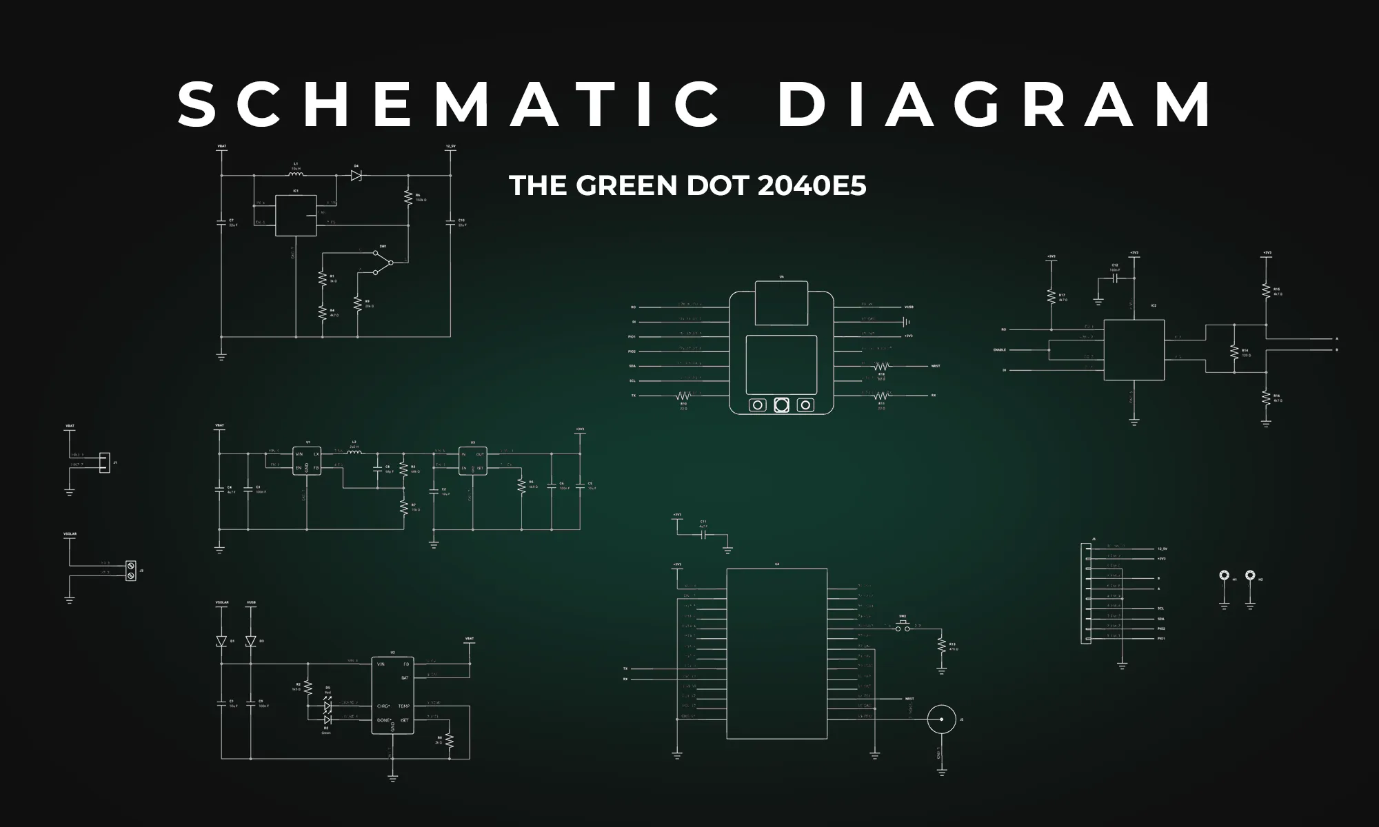
Explore the essentials of schematic diagrams in our comprehensive guide, covering everything from basic resistors to complex integrated circuits, and learn to master the visual language of electronics.

Looking for a comprehensive guide to ESP8266 pinout? Check out our article that covers everything you need to know about the ESP8266's pins, including digital, analog, and PWM pins. Perfect for beginners and experts alike, our guide will help you understand the ESP8266's pinout and how to use it in your projects.


Effortlessly calculate parallel and series resistor values with our accurate, user-friendly tool designed to optimize circuit performance and streamline electrical design processes.

One of the key components of PCBs are vias, which are tiny pathways that allow electrical signals to travel from one layer of the board to another. Vias are a staple of PCB design.

Focusing on Arduino Mega, Micro, and Uno, the blog details how the Mega 2560 stands out with its extensive memory and numerous I/O pins for sophisticated projects.

We’ve been so amazed with the ways you’ve used Copilot to brainstorm, debug, and conduct part research that we’ve compiled some of our favorite prompts you can copy and paste, or modify for your own use!

The Raspberry Pi Zero 2 W is a small and powerful computer with impressive performance for its size and price. With a quad-core processor, 512MB of RAM, built-in wireless connectivity, and a USB On-The-Go port, it's suitable for many projects, including home automation, media centers, and robotics.

Explore the world of Arduino with a step-by-step guide on writing your first code and setting up a fundamental 'Blink' project to bring electronics to life.

Discover how CAD Librarians can leverage Flux’s key capabilities—AI Part Imports, Component Updates, Live Pricing, and JEP30 Export—each tailored to meet the specific demands of maintaining PCB libraries.

The guide provides an easy-to-follow formula for converting mm to mils, essential in engineering and PCB design for precise measurements and applications.

Avoid costly errors in your PCB design with these expert tips! Discover the 5 most common mistakes in trace width, vias, power planes, and more. Learn how Flux’s AI Copilot helps you catch these issues early, ensuring your board is ready for manufacturing.