February 4, 2023
Raspberry Pi Pinouts: A Comprehensive Guide
Share

The Raspberry Pi is a popular single-board computer that is widely used for various projects and applications, such as media centers, home automation, and gaming. In this article, we will provide a comprehensive guide to the Raspberry Pi pinout diagram, including a description of each pin and its functions.
The Raspberry Pi comes with a 40-pin header that provides access to the GPIO, I2C, SPI, UART, and power pins. The header is located on the top-left corner of the board, and it is designed to be compatible with various add-on boards, known as "HATs" (Hardware Attached on Top). The pinout diagram of the Raspberry Pi is shown in table below.

The GPIO (General Purpose Input/Output) pins on the Raspberry Pi can be controlled using software, such as Python or C, to interface with various devices and sensors. To control the GPIO pins, you need to install a library that provides access to the GPIO pins and allows you to write code to control them. One of the most commonly used libraries for controlling GPIO pins on the Raspberry Pi is RPi.GPIO, which is a Python library that provides easy access to the GPIO pins. To use RPi.GPIO, you need to first install it using the following command in the terminal:
Once installed, you can import the library in your Python script and use it to control the GPIO pins. For example, the following code sets up a GPIO pin as an output and turns it on:
In this example, the GPIO.setmode(GPIO.BOARD) line sets the numbering mode to use the physical pin numbers on the header. The GPIO.setup(7, GPIO.OUT) line sets up the GPIO pin 7 as an output, and the GPIO.output(7, GPIO.HIGH) line sets the output to high, turning on the pin.
It is important to note that when controlling the GPIO pins, you need to be careful and follow the recommended procedures, as incorrect use can cause damage to the Raspberry Pi or other connected devices. Always refer to the datasheet of the devices you are connecting to the Raspberry Pi to ensure that you are using the correct voltage levels and pin configurations.
The power pins on the Raspberry Pi are used to provide power to the board and connected devices. There are a total of 4 power pins, which include:
SDA and SCL are two pins on the Raspberry Pi header that are used for communication with I2C (Inter-Integrated Circuit) devices. SDA stands for Serial Data Line, and it is used for transmitting data between the Raspberry Pi and the I2C device. SCL stands for Serial Clock Line, and it provides the clock signal that synchronizes the communication between the Raspberry Pi and the I2C device.
I2C is a multi-slave serial communication protocol, which means that multiple devices can be connected to the same two lines (SDA and SCL), and each device can be addressed individually. The Raspberry Pi supports I2C communication, which allows for easy interfacing with various I2C devices, such as sensors, displays, and other peripherals.
By using the SDA and SCL pins, electrical engineers can communicate with I2C devices and integrate them into their Raspberry Pi projects, making it possible to add new functionality and capabilities to the board. The I2C (Inter-Integrated Circuit) pins on the Raspberry Pi are used to communicate with I2C devices, such as sensors, displays, and actuators. There are a total of 2 I2C pins on the Raspberry Pi header, which include:
The SPI (Serial Peripheral Interface) pins on the Raspberry Pi are used to communicate with SPI devices, such as displays, sensors, and actuators. There are a total of 3 SPI pins on the Raspberry Pi header, which include:
The UART (Universal Asynchronous Receiver/Transmitter) pins on the Raspberry Pi are used to communicate with UART devices, such as GPS modules, Bluetooth modules, and other serial devices. There are a total of 2 UART pins on the Raspberry Pi header, which include:
PWM (Pulse Width Modulation) is a technique used to control the amount of power delivered to an electrical device by switching it on and off rapidly. On the Raspberry Pi, some of the GPIO pins can be used as PWM pins, allowing you to generate PWM signals and control the power delivered to external devices.
The following GPIO pins on the Raspberry Pi can be used as PWM pins: 12 (GPIO 18), 13 (GPIO 27), 18 (GPIO 5), 19 (GPIO 6), 40 (GPIO 21), 41 (GPIO 20), 45 (GPIO 28), and 52 (GPIO 3). These pins are capable of hardware PWM, which means that the PWM signals are generated directly by the hardware, providing high-precision control over the PWM frequency and duty cycle.
To use the PWM pins on the Raspberry Pi, you need to use a library that provides access to the PWM functionality. The RPi.GPIO library, which was introduced in a previous answer, also provides support for PWM. To use PWM with RPi.GPIO, you need to first set up the pin as a PWM output and then start the PWM signal. For example, the following code sets up a GPIO pin as a PWM output and generates a 50Hz PWM signal with a duty cycle of 25%:
In this example, the GPIO.PWM(12, 50) line creates a PWM object for the GPIO pin 12 with a frequency of 50Hz. The p.start(25) line starts the PWM signal with a duty cycle of 25%. You can change the duty cycle by calling the ChangeDutyCycle method, which allows you to control the power delivered to the device.
It is important to note that the number of PWM pins on the Raspberry Pi is limited, and if you need more PWM outputs, you may need to use an external PWM controller or a multiplexer to expand the number of available PWM pins.
Yes, all Raspberry Pi boards have the same 40-pin header, with the same pinout, with the exception of the Raspberry Pi Zero and Zero W, which have a smaller header with a slightly different pinout. The pinout of the Raspberry Pi header is standardized, which means that all of the GPIO, I2C, SPI, UART, and power pins are in the same location on all Raspberry Pi boards. This allows for compatibility between different Raspberry Pi models and makes it easier for users to use add-on boards and interface with various devices and sensors.
Yes, the Raspberry Pi 3 and 4 have the same 40-pin header with the same pinout. The only difference between the two is the layout of the pins, with the Raspberry Pi 4 having a slight rearrangement compared to the Raspberry Pi 3. However, the functionality of the pins remains the same, and all of the GPIO, I2C, SPI, UART, and power pins are in the same location on both boards. This allows for compatibility between the Raspberry Pi 3 and 4 and makes it easier for users to use add-on boards and interface with various devices and sensors on either board.
The Raspberry Pi pinout diagram is a critical component of the board, as it provides access to the GPIO, I2C, SPI, UART, and power pins. This comprehensive guide has described each of the 40 pins on the Raspberry Pi header, including their functions and usage. Understanding the Raspberry Pi pinout diagram is crucial for electrical engineers, as it allows them to interface with various devices and sensors, and to create innovative projects and applications.
Whether you’re experimenting with an ATmega328 for your first Arduino project or building a cutting-edge ESP32-based IoT device, designing a custom PCB will take your project to the next level. Flux makes it easy with an intuitive interface, smart design tools, and access to a huge component library. No matter your experience level, Flux helps you create PCBs quickly and efficiently, without the usual headaches.
Get started today—sign up for Flux and bring your ideas to life!


Learn about STM32 microcontrollers, popular series, USB OTG, SWD, UART, and development tools. Find the right STM32 MCU and kickstart your projects.

Looking for a comprehensive guide to ESP8266 pinout? Check out our article that covers everything you need to know about the ESP8266's pins, including digital, analog, and PWM pins. Perfect for beginners and experts alike, our guide will help you understand the ESP8266's pinout and how to use it in your projects.

Looking for a comprehensive guide to ESP32 pinout? Check out our article that covers everything you need to know about the ESP32's pins, including digital, analog, PWM, and Strapping pins. Perfect for beginners and experts alike, our guide will help you understand the ESP32's pinout and how to use it in your projects.
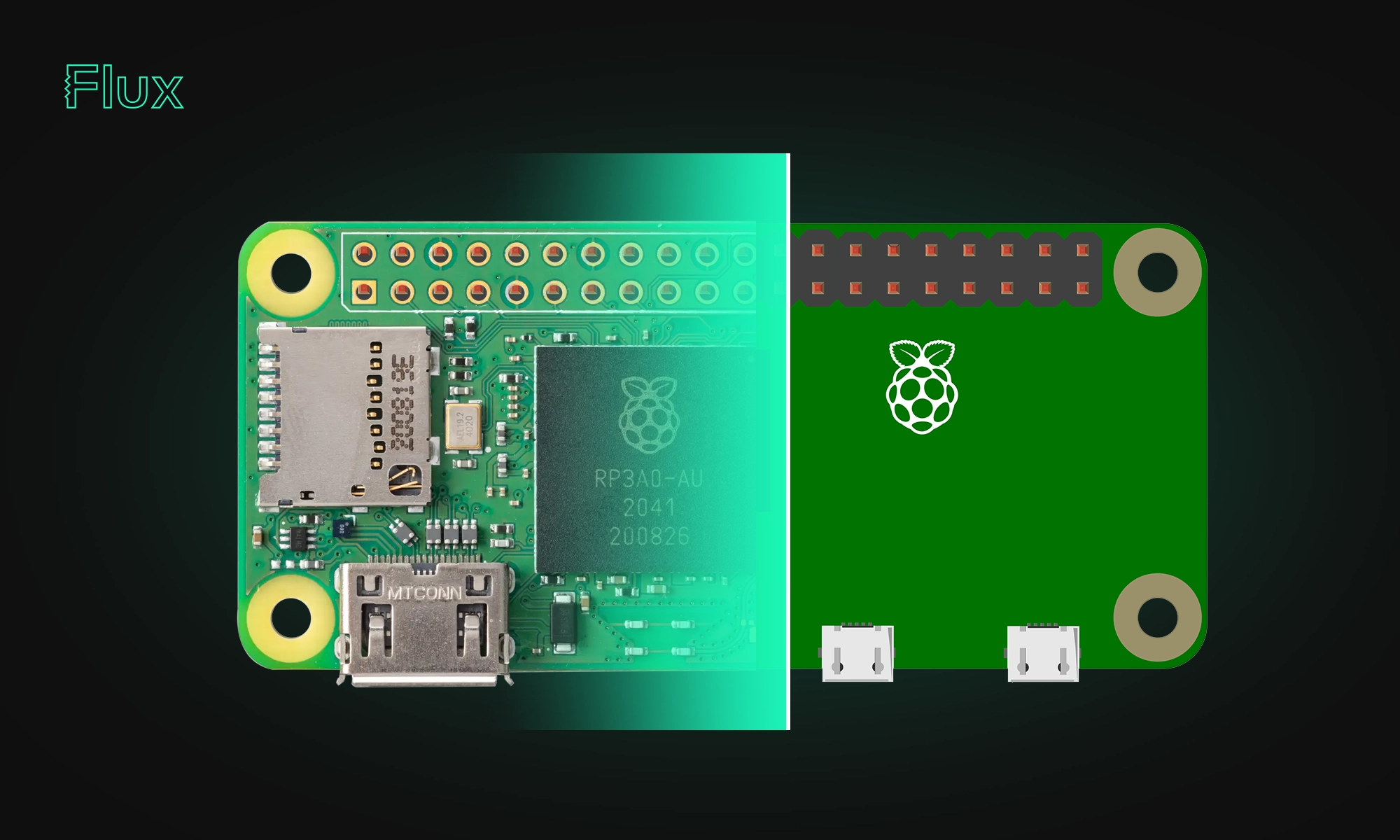
The Raspberry Pi Zero 2 W is a small and powerful computer with impressive performance for its size and price. With a quad-core processor, 512MB of RAM, built-in wireless connectivity, and a USB On-The-Go port, it's suitable for many projects, including home automation, media centers, and robotics.
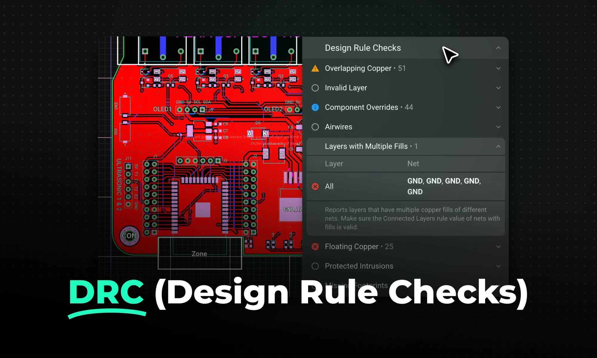
DRC is an automated process that checks your PCB layout against manufacturing and electrical constraints, catching errors like trace spacing and drill sizes before fabrication. Modern tools run this in real-time during design, while older ones batch-check at the end, often producing overwhelming error lists.

Arduino Nano R4 packs UNO R4 performance into Nano size. Learn specs, standout features, and who should upgrade in this in-depth guide.

RP2350 A4 fixes GPIO bug, hardens security, adds 5 V tolerance and on-chip flash. See why every Pico project should migrate.

This post explains key signal integrity issues like crosstalk and reflections in PCBs and offers simple layout tips to avoid them. A free guide is included.


