November 22, 2023
Understanding Schematic Diagrams: a Comprehensive Guide
Share
BuildWithFlux


A curated collection of PCB and hardware projects crafted by our talented Flux community.
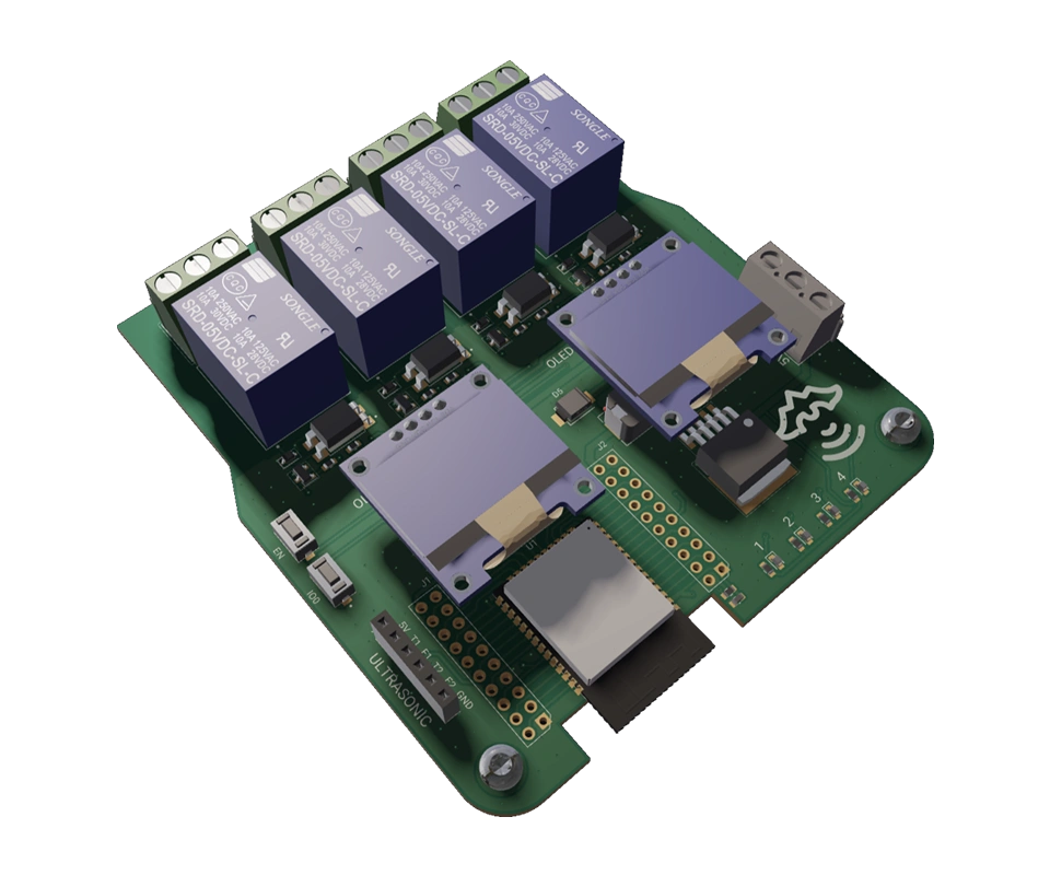
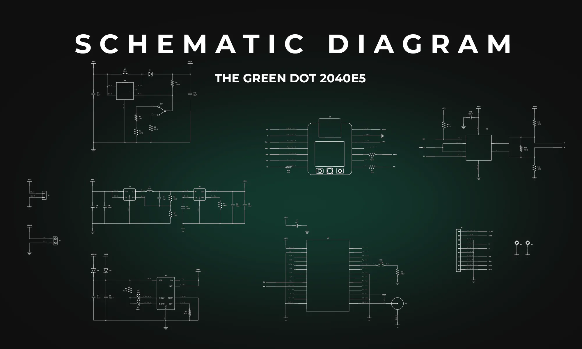
A schematic diagram abstracts the complexity of an electrical circuit into a more digestible form, using standardized symbols to represent various components like capacitors, diodes, and logic gates. These diagrams function as the visual language of electronics, allowing engineers to communicate intricate circuit details efficiently. Without a well-designed schematic, even the most brilliant circuit ideas risk becoming an impractical jumble of components.
All components have their own designators and symbols that help schematic designs define the interconnections of their electric circuit.
The mastery of schematic diagrams is more than a mere technical skill; it's a vital competency that can make or break your designs. The intricacies of each symbol, from the humble resistor to complex integrated circuits, combine to form the language of electronics. Fluent communication in this language enables you to translate creative concepts into functional, reliable circuits. By investing in a deeper understanding of each component and its schematic representations, you position yourself for more insightful design, efficient problem-solving, and ultimately, better-engineered solutions.


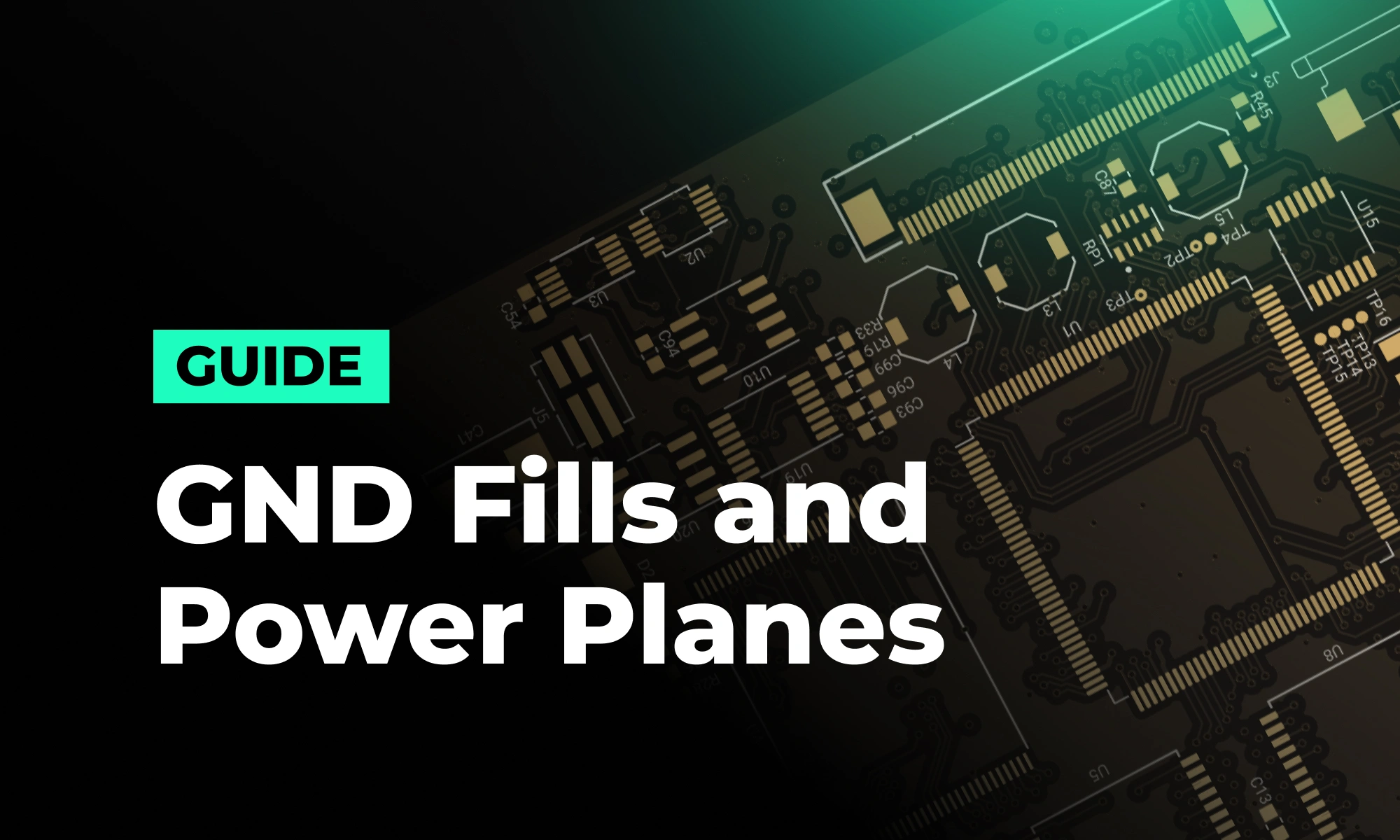
In this post, we’ll explore why these concepts matter, how they impact signal integrity and power distribution, and what to keep in mind as you design. If you want to go deeper into implementation details—like when to use zones, where to place stitching vias, or how to avoid stack-up pitfalls—we’ve created a detailed PDF guide just for that.
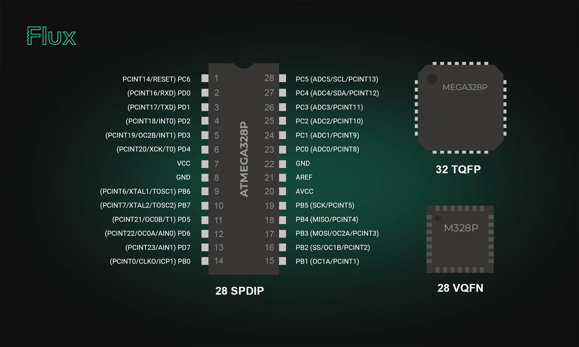
The ATmega328p stands out in the microcontroller world; our post breaks down its datasheet and pinout, offering valuable insights into its functionality and versatility. Learn how this powerful microcontroller can enhance your projects.

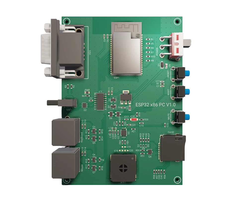
ESP32 microcontrollers are affordable, low-power SoCs with integrated Wi-Fi and Bluetooth. Offering dual-core processing, ample memory, and versatility, they excel in IoT, wearables, and smart home applications. The ESP32's continuous evolution promises exciting possibilities ahead.

Think you're familiar with the push button and its symbol? Prepare to be surprised! Join us in our latest blog post where we unravel the intricate science behind every press, click, and circuit, revealing the complexities hidden in the simplicity of a push button switch.
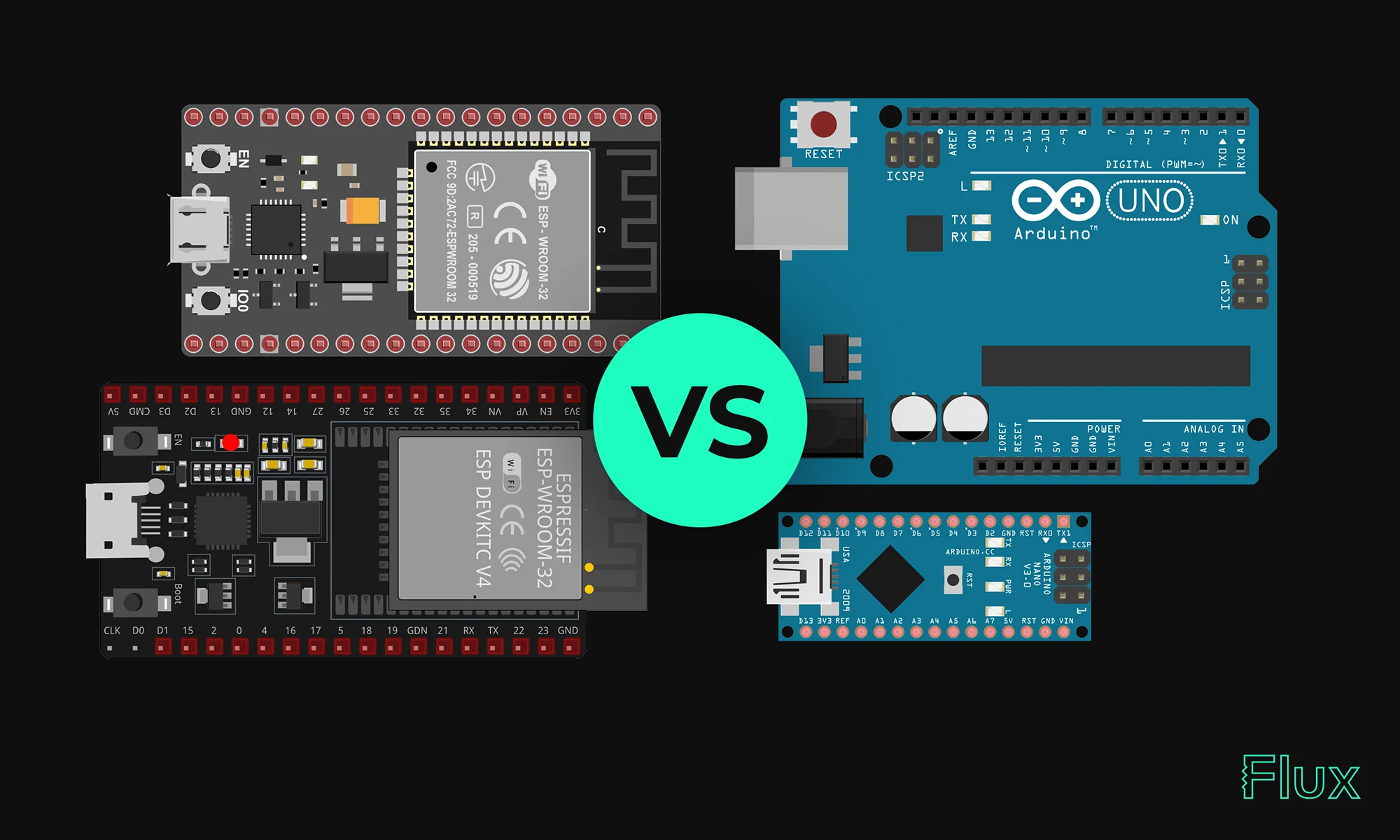
Our 2023 guide compares ESP32 and Arduino, two essential microcontrollers in IoT. ESP32 offers advanced features like Wi-Fi, while Arduino excels in ease of use and community support. Choose based on your project's complexity and needs.

Today, we're proud to announce a significant upgrade to Flux Copilot: Copilot can now understand datasheets and reference them in its responses. This means you get more accurate responses when asking Copilot questions about specific parts. This enables you to directly utilize the wealth of data often hidden in the layers of these dense technical documents.
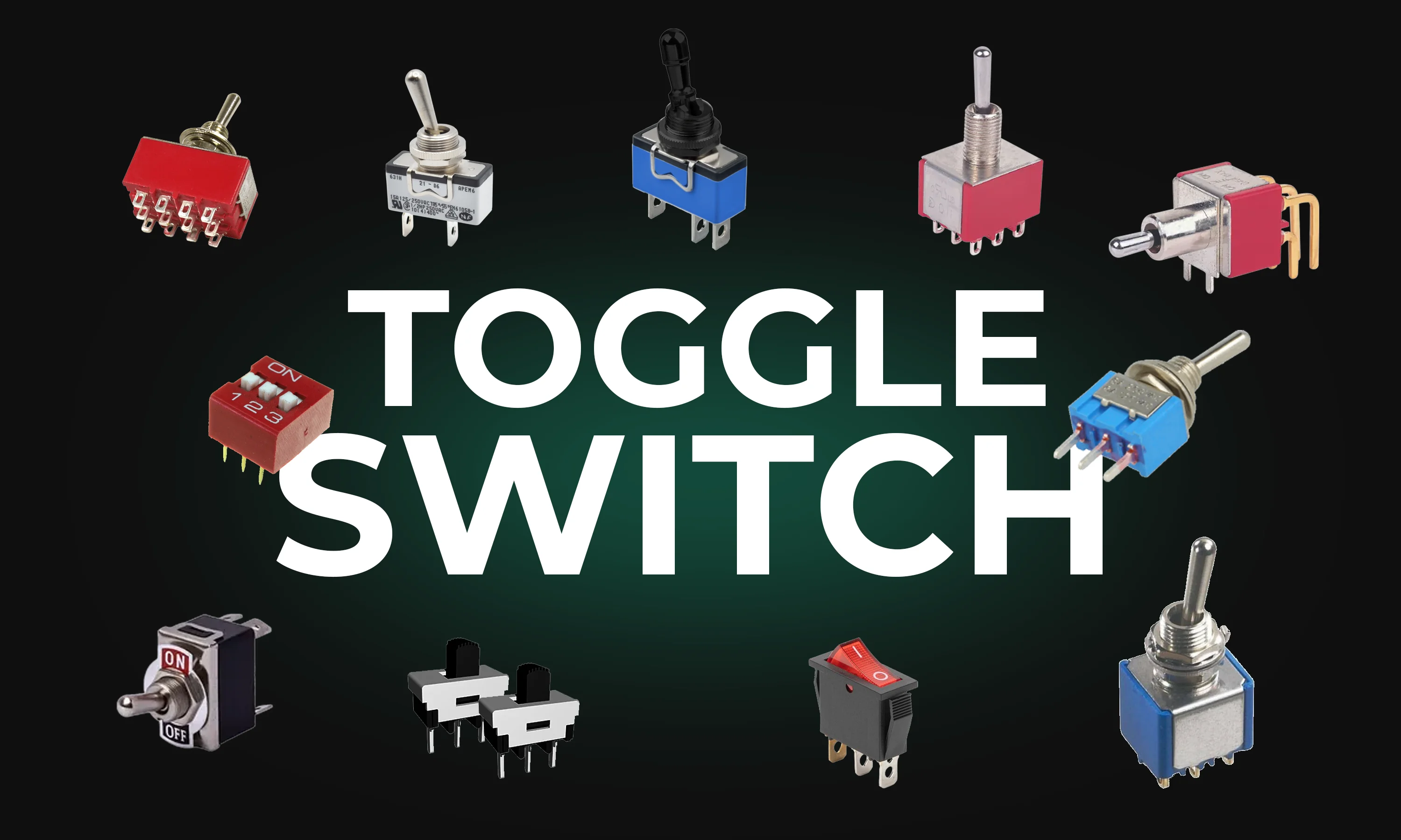
This guide explores toggle switches, their types, and applications in electronics. Learn how they work and find the right one for your project.
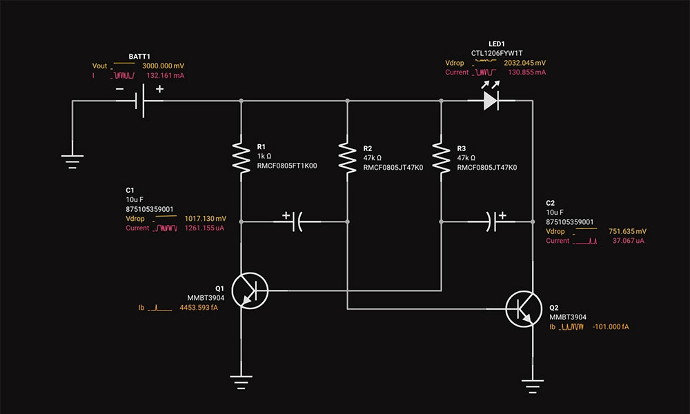
Circuit simulation is a crucial tool in electronic design. It uses software to predict how circuits will perform, saving time and money. Popular options like Flux, LTSpice, and CircuitMaker offer powerful features.

The guide provides an easy-to-follow formula for converting mm to mils, essential in engineering and PCB design for precise measurements and applications.
Learn about STM32 microcontrollers, popular series, USB OTG, SWD, UART, and development tools. Find the right STM32 MCU and kickstart your projects.

Imagine designing a PCB in a third less time than you're used to - that's the power of Flux Copilot's new upgrade, allowing it to wire components together for you. In this tutorial, we'll walk you through the important workflows and example prompts to help you design a Raspberry-Pi-Pico-like board in 20 minutes.


This blog post explores the RS485 communication standard, renowned for its ability to facilitate long-distance, multidrop networking with enhanced noise immunity, making it a preferred choice for industrial settings. Dive into the post to understand RS485's key features and advantages over older protocols.