March 2, 2023
ESP32 Pinout: Everything You Need to Know
Share

ESP32 is a dual-core SoC with two powerful Xtensa LX6 CPUs that run at up to 240 MHz. It comes with integrated Wi-Fi and Bluetooth connectivity, making it suitable for a wide range of IoT applications that require wireless connectivity. ESP32 is the successor of the popular ESP8266 chip, and it offers a lot more capabilities and functionality.
ESP32 also includes various peripherals such as SPI, I2C, UART, ADC, DAC, PWM, and GPIO, which makes it highly adaptable and suitable for a wide range of projects ranging from low-power sensor networks to the most demanding tasks, such as voice encoding, music streaming and MP3 decoding.
One of the most significant advantages of ESP32 is its low power consumption. It has a deep-sleep mode that can reduce the power consumption to as low as 5 microamps, which is ideal for battery-powered applications. ESP32 also has a built-in voltage regulator that can operate on a wide range of power supplies, from 2.2V to 3.6V, which makes it easy to power and use.
Yes, the ESP32 has digital pins, also known as General Purpose Input/Output (GPIO) pins. These pins are used for digital input and output and can be configured as either inputs or outputs depending on the needs of the project. The ESP32 has a total of 36 GPIO pins that can be used for various purposes, including interfacing with sensors, controlling LEDs, and communicating with other devices.
NOTE: not all GPIOs are accessible in all development boards, but each specific GPIO works in the same way regardless of the development board you’re using. For ESP32 DEVKIT V1 board, GPIO6 to GPIO11 are connected to the integrated SPI flash and are not recommended for other uses.
The ESP32 is a 3.3V device, which means that all of its input and output pins are designed to operate with a maximum voltage of 3.3 volts. Connecting the ESP32 to a voltage source greater than 3.3 volts can damage the device, so it's important to use level shifters or voltage dividers when interfacing with higher voltage devices.
It's also important to note that the power supply for the ESP32 should be 3.3V DC. Some development boards or modules may have built-in voltage regulators that can accept a higher input voltage (such as 5V) and regulate it down to 3.3V for the ESP32, but it's always best to check the specifications of the specific device you are using to ensure proper voltage supply.
These pins don’t have internal pull-up or pull-down resistors. They can’t be used as outputs, so use these pins only as inputs:
To utilize these pins in Arduino IDE, and you want to make GPIO 22 as input and GPIO 23 as output:
pinMode() configures the specified pin to behave either as an input (with or without an internal weak pull-up or pull-down resistor), or an output. It is possible to enable the internal pullup resistors with the mode INPUT_PULLUP. Additionally, the INPUT mode explicitly disables the internal pullups.
There are three serial ports on the ESP32 known as U0UXD, U1UXD and U2UXD all work at 3.3V TTL Level. There are three hardware supported serial interfaces on the ESP32 known as UART0, UART1 and UART2. Like all peripherals, the pins for the UARTs can be logically mapped to any of the available pins on the ESP32. However, the UARTs can also have direct access which marginally improves performance. The pin mapping table for this hardware assistance is as follows.
Strapping pins are used to put the ESP32 into bootloader or flashing mode. On most development boards with built-in USB to SERIAL, you don't need to worry about the state of these pins. The board itself puts the pins in the right state prior to flashing or when on boot mode.
Some GPIOs change their state to HIGH or output PWM signals at boot or reset. This means that if you have outputs connected to these GPIOs you may get unexpected results when the ESP32 resets or boots.
NOTE: If you have peripherals connected to these pins, you may encounter issues with trying to upload new code, flashing the ESP32 with new firmware, or resetting the board, it may be because those peripherals are preventing the ESP32 from entering the right mode.
The ESP32 has two I2C channels and any pin can be set as SDA or SCL. When using the ESP32 with the Arduino IDE, the default I2C pins are:
You can use the wire library to use other pins for I2C, you just need to call:
These are the default pin mapping for SPI
GPIO 6 to GPIO 11 are exposed in some ESP32 development boards. However, these pins are connected to the integrated SPI flash on the ESP-WROOM-32 chip and are not recommended for other uses. So, don’t use these pins in your projects:
Goodnews. All ESP32 GPIO pins are interrupt-capable (interrupts) pins. You can enable the interrupt functionality to any GPIO input pin using this function from the Arduino Core.
Enable (EN) is the 3.3V regulator’s enable pin. It’s pulled up, so connect to ground to disable the 3.3V regulator. This means that you can use this pin connected to a pushbutton to restart your ESP32, for example.
The ESP32 has built-in Analog to Digital Converters (ADC) that allow it to convert analog signals into digital values that can be processed by the digital circuits on the chip. The ESP32 has a total of 18 ADC channels, which can be used to read analog signals from various sensors, such as temperature sensors, light sensors, and other types of sensors that output analog signals.
The ESP32's ADC has a resolution of 12 bits, which means that it can measure the analog signal and convert it into a digital value between 0 and 4095. The ADC can also be configured to sample the analog signal at different rates and can be programmed to read multiple channels simultaneously.
The ESP32 has 18 x 12 bits ADC input channels (while the ESP8266 only has 1x 10 bits ADC). These are the GPIOs that can be used as ADC and respective channels:
There are 2 x 8 bits DAC channels on the ESP32 to convert digital signals into analog voltage signal outputs. These are the DAC channels:
The ESP32 has 10 capacitive touch GPIOs. These GPIOs can sense variations in anything that holds an electrical charge, like the human skin. So they can detect variations induced when touching the GPIOs with a finger.
These pins can be easily integrated into capacitive pads, and replace mechanical buttons. Additionally, the touch pins can also be used as a wake up source when the ESP32 is in deep sleep.
To use the ESP32 touch sensor in Arduino:
Reading the touch sensor is straightforward. You use the touchRead() function, that accepts as argument, the GPIO you want to read.
This example arduino sketch reads the touch pin 0 and displays the results in the Serial Monitor.
There is RTC GPIO support on the ESP32. The GPIOs routed to the RTC low-power subsystem can be used when the ESP32 is in deep sleep. These RTC GPIOs can be used to wake up the ESP32 from deep sleep when the Ultra Low Power (ULP) co-processor is running. The following GPIOs can be used as an external wake up source.
The ESP32 pulse width modulation PWM controller has 16 independent channels that can configured to generate PWM signals with different configuration and properties that can be used for controlling the intensity of digital signals, such as LEDs and Motors. PWM is a technique that allows the duty cycle of a digital signal to be varied, which in turn changes the average voltage and current delivered to the load.
The PWM frequency can be set using the ledcSetup() and ledcAttachPin() functions, which allow you to configure the PWM frequency and attach the PWM pin to a specific output.
In addition to the 16 hardware PWM pins, the ESP32 also supports software-based PWM, which can be used to control additional PWM channels on any GPIO pin. The ESP32's software PWM uses a technique called bit-banging, which allows the duty cycle of a digital signal to be varied by software.


Learn about STM32 microcontrollers, popular series, USB OTG, SWD, UART, and development tools. Find the right STM32 MCU and kickstart your projects.

Looking for a comprehensive guide to ESP8266 pinout? Check out our article that covers everything you need to know about the ESP8266's pins, including digital, analog, and PWM pins. Perfect for beginners and experts alike, our guide will help you understand the ESP8266's pinout and how to use it in your projects.

The Raspberry Pi Zero 2 W is a small and powerful computer with impressive performance for its size and price. With a quad-core processor, 512MB of RAM, built-in wireless connectivity, and a USB On-The-Go port, it's suitable for many projects, including home automation, media centers, and robotics.
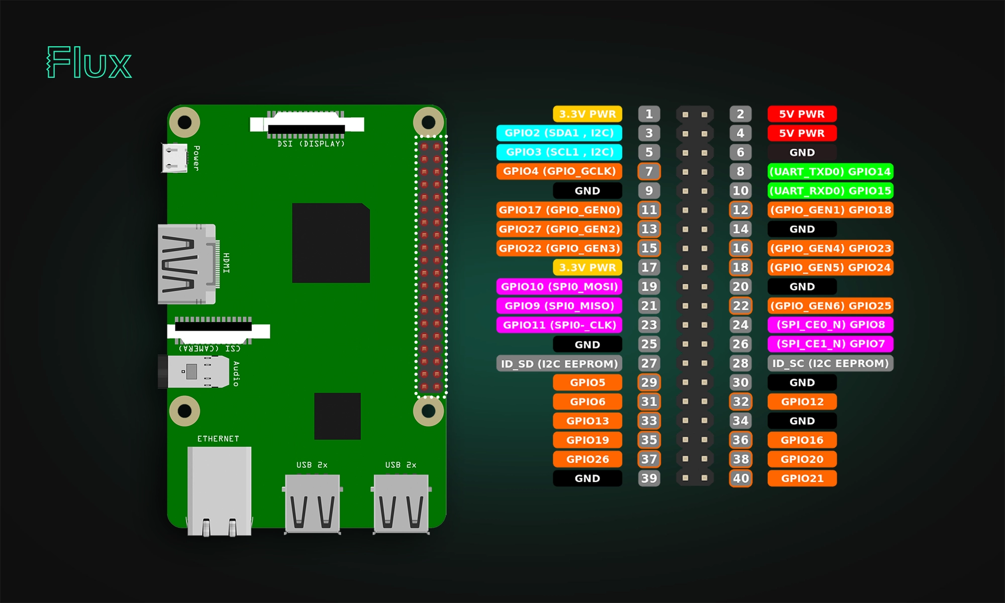
In this article, we will provide a comprehensive guide to the Raspberry Pi pinout diagram, including a description of each pin and its functions.

DRC is an automated process that checks your PCB layout against manufacturing and electrical constraints, catching errors like trace spacing and drill sizes before fabrication. Modern tools run this in real-time during design, while older ones batch-check at the end, often producing overwhelming error lists.

Arduino Nano R4 packs UNO R4 performance into Nano size. Learn specs, standout features, and who should upgrade in this in-depth guide.

RP2350 A4 fixes GPIO bug, hardens security, adds 5 V tolerance and on-chip flash. See why every Pico project should migrate.

This post explains key signal integrity issues like crosstalk and reflections in PCBs and offers simple layout tips to avoid them. A free guide is included.


