September 16, 2023
Explore the Advantages of Buck and Boost Converter in Modern Electronics
Share

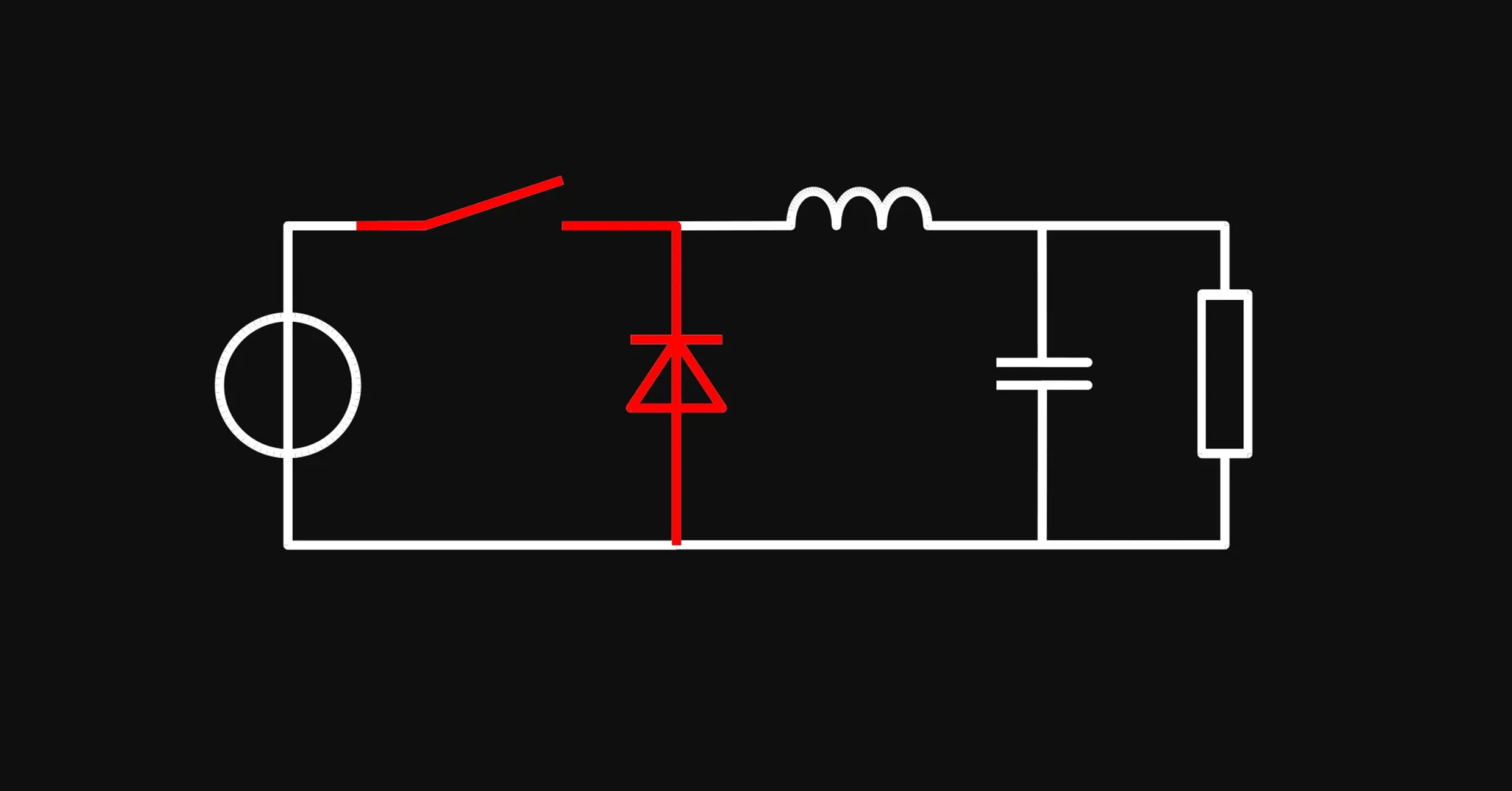
A Buck converter serves as a step-down DC-DC converter, adept at transforming a higher input voltage to a lower, regulated output voltage (Vout). The core components include an inductor, a diode, a switch (commonly a MOSFET), and a capacitor. By modulating the pulse-width modulation (PWM) duty cycle of the MOSFET, the Buck converter fine-tunes the Vout.
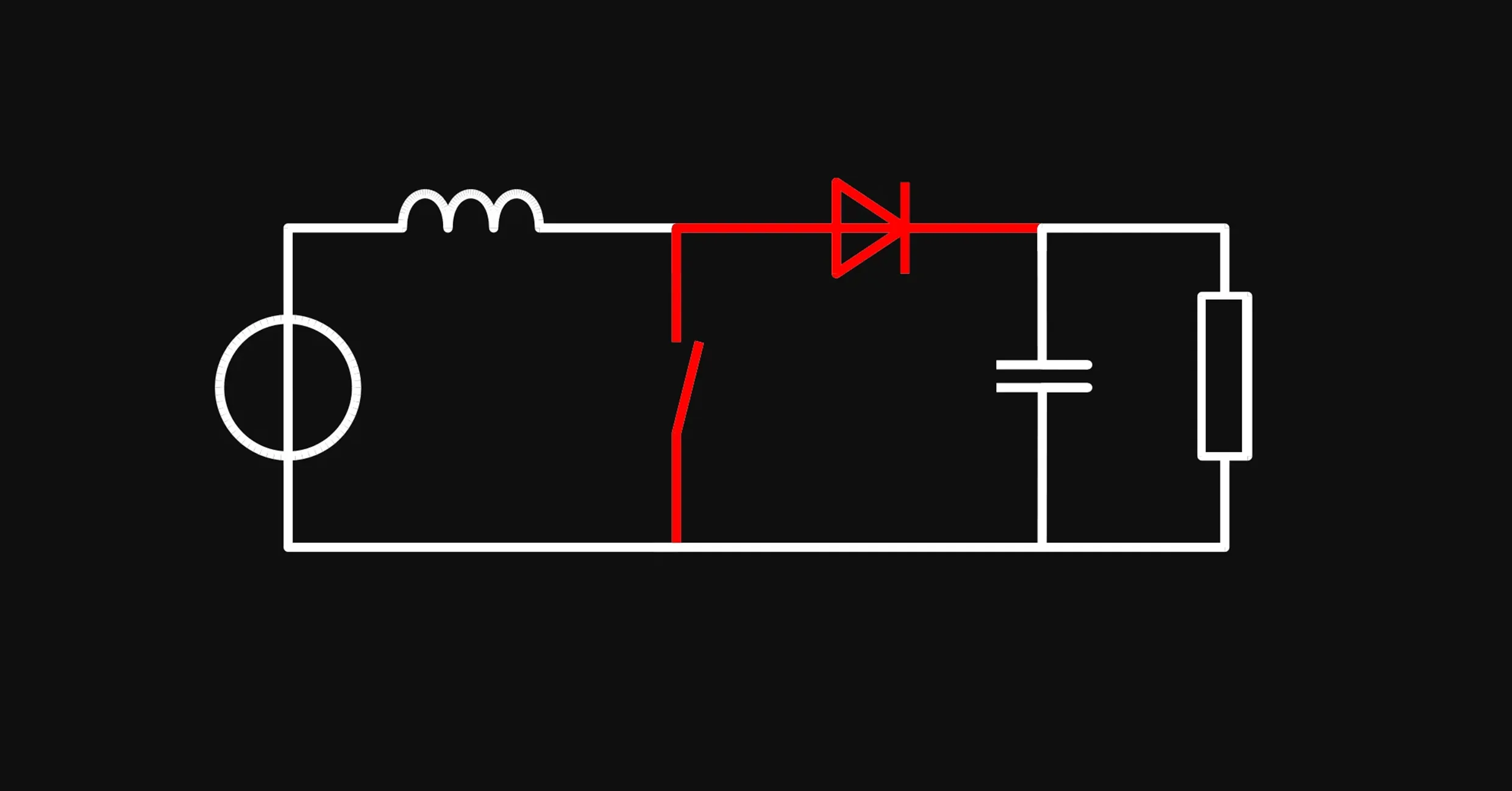
In contrast to the Buck converter, a Boost converter acts as a step-up DC-DC converter. It elevates a lower input voltage to a higher Vout. The essential components—inductor, diode, MOSFET, and capacitor—are arranged differently to achieve this function.
For systems that require both step-up and step-down voltage regulation, Buck-Boost and Sepic (Single-Ended Primary Inductor Converter) converters offer a flexible solution. They can function as either a Buck or a Boost converter, depending on the input voltage and system demands.
Flyback converters are useful for applications requiring isolated outputs, while inverting converters can invert the polarity of the output voltage, expanding the range of potential applications.
Buck and Boost converters, as specialized DC-DC converters, have become irreplaceable in the realm of modern electronics. Using simple components and concepts, like inductors, capacitors, MOSFETs, and PWM control, Buck and Boost converters work miracles for power circuits. Their unique advantages in terms of efficiency, versatility, and compactness make them indispensable in shaping the future of power management solutions.


Fast charging has come a long way—and one of the most advanced technologies in this space is Programmable Power Supply (PPS). If you’ve ever wondered why your device charges faster with some cables and adapters than others, PPS might be the answer.

Arduino Nano R4 packs UNO R4 performance into Nano size. Learn specs, standout features, and who should upgrade in this in-depth guide.
RP2350 A4 fixes GPIO bug, hardens security, adds 5 V tolerance and on-chip flash. See why every Pico project should migrate.

CO2 sensors monitor air quality, helping prevent cognitive decline from high CO2 levels. They use various technologies for accuracy in different settings. These sensors are vital for health, efficiency, and safety.

We're excited to unveil our Smart Polygon system in Flux! This powerful capability builds on top of our automatic copper fills to transform how you create and manage custom copper areas in your PCB designs.
Learn about STM32 microcontrollers, popular series, USB OTG, SWD, UART, and development tools. Find the right STM32 MCU and kickstart your projects.
Discover how CAD Librarians can leverage Flux’s key capabilities—AI Part Imports, Component Updates, Live Pricing, and JEP30 Export—each tailored to meet the specific demands of maintaining PCB libraries.

Copilot new access to Flux’s live pricing and availability tools so that it can do the supply chain and cost analysis for you. Read on to learn about how we’re leveraging AI to give you the power of an entire supply-chain team right at your fingertips.
