November 3, 2023
ESP8266 Pinout Guide: Complete GPIO Reference & IoT Project Tips
Share

In this guide, we’ll walk through:
The ESP8266 is a low-cost Wi-Fi microcontroller by Espressif. It enables wireless IoT projects without needing a separate Wi-Fi module. Popular boards like the NodeMCU and Wemos D1 Mini use it as their core.
The ESP8266 microcontroller module features a total of 32 pins, each with a function that contributes to its remarkable utility. Here, we'll break down these key specifications to provide a clear understanding of its pinout:
The ESP8266 features 32 pins, but not all are usable for general I/O. Here’s a breakdown:
You can power ESP8266 directly via the USB connector (standard USB = 5V) or the Vin pin (5V to 10V). The regulator provides a maximum of 500mA.
These are the power pins of this microcontroller board:
It's essential to realize that the GPIO labeling on the ESP8266 does not correspond directly to the silkscreen markings on the board. For instance, the pin marked as D0 is actually GPIO16, while the one labeled D1 is in fact GPIO5.
The table below outlines the relationship between the silkscreen labels on the board and the actual GPIO numbers, detailing the most suitable pins for your projects and highlighting those that require careful handling.
GPIO6 to GPIO11 are usually connected to the flash chip in ESP8266 boards. So, these pins are not recommended to use.
The ESP8266 can be prevented from booting if some pins are pulled LOW or HIGH. The following list shows the state of the following pins during BOOT:
ESP8266 only has one analog input, it's the ADC0 pin, usually labelled as A0 on the board. If you're using the bare ESP8266 chip, the maximum input voltage range of this ADC0 is 0 to 1V, for development board like NodeMCU ESP8266 12-E, the voltage input range is 0 to 3.3V due to presence of internal voltage divider.
This ADC pin has a 10-bit resolution, which means you’ll get values between 0 and 1023.
Unlike other microcontrollers, the ESP8266 lacks dedicated hardware for I2C; however, I2C functionality can be implemented in software, allowing any GPIOs to be used for I2C purposes. Commonly, the following GPIOs are used as I2C pins:
The pins used as SPI in the ESP8266 are:
The ESP8266 supports interrupts in any GPIO, except GPIO16.
The GPIO pins on the esp8266 are the backbone of its versatility, allowing you to connect various components to create a wide array of IoT applications. To illustrate their practical utility, let's consider a simple project: building a weather monitoring station.
And with the many additional pinouts, our weather monitoring station can always be improved--add a temperature sensor to GPIO2, or a humidity sensor to GPIO3!
The esp8266 pinout is also perfect for developers who are already comfortable with the Arduino IDE, as they seamlessly integrate, making the esp8266 widely accessible.
Using the Arduino IDE with the esp8266 offers several benefits:

When it comes to practical application, the Wemos D1 Mini, built around the esp8266, is a favorite among developers. Its compact size, affordability, and extensive support from the maker community have made it a go-to choice for IoT projects.
Here are some reasons why the Wemos D1 Mini is an excellent choice:
In the evolving landscape of IoT, the esp8266 pinout is highly versatile. Its GPIO pins, compatibility with Arduino IDE, I2C capabilities, and integration into popular development boards like the Wemos D1 Mini provide a robust foundation for your IoT projects. However, if you're looking for something more, then check out its sibling, the esp32. The esp32 retains the flexibility of the esp8266 pinout while offering more processing power, built-in Bluetooth, and dual-core processing. This opens up new opportunities for more complex and feature-rich IoT applications.


Learn about STM32 microcontrollers, popular series, USB OTG, SWD, UART, and development tools. Find the right STM32 MCU and kickstart your projects.

Looking for a comprehensive guide to ESP32 pinout? Check out our article that covers everything you need to know about the ESP32's pins, including digital, analog, PWM, and Strapping pins. Perfect for beginners and experts alike, our guide will help you understand the ESP32's pinout and how to use it in your projects.

The Raspberry Pi Zero 2 W is a small and powerful computer with impressive performance for its size and price. With a quad-core processor, 512MB of RAM, built-in wireless connectivity, and a USB On-The-Go port, it's suitable for many projects, including home automation, media centers, and robotics.

In this article, we will provide a comprehensive guide to the Raspberry Pi pinout diagram, including a description of each pin and its functions.
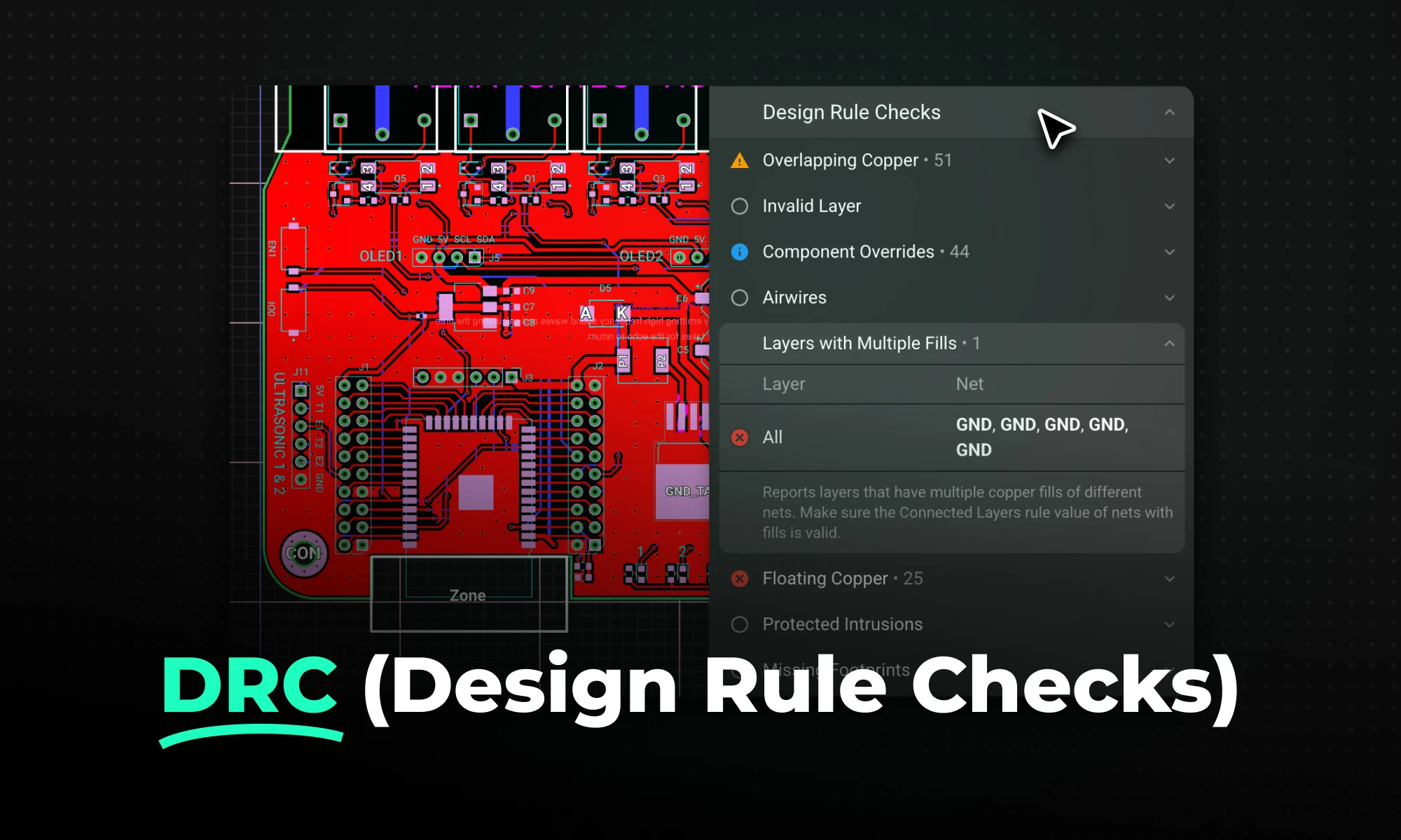
DRC is an automated process that checks your PCB layout against manufacturing and electrical constraints, catching errors like trace spacing and drill sizes before fabrication. Modern tools run this in real-time during design, while older ones batch-check at the end, often producing overwhelming error lists.

Arduino Nano R4 packs UNO R4 performance into Nano size. Learn specs, standout features, and who should upgrade in this in-depth guide.
RP2350 A4 fixes GPIO bug, hardens security, adds 5 V tolerance and on-chip flash. See why every Pico project should migrate.

This post explains key signal integrity issues like crosstalk and reflections in PCBs and offers simple layout tips to avoid them. A free guide is included.


