February 7, 2023
Arduino Uno Schematic Diagram: A Comprehensive Guide
Share

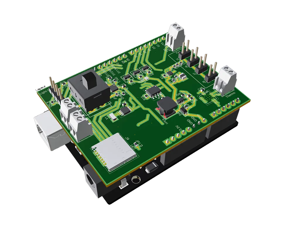
The Arduino Uno is a microcontroller board that is widely used by hobbyists and electrical engineers due to its ease of use and versatility. It is based on the ATmega328P microcontroller and features a comprehensive pinout that provides access to various peripheral interfaces, including I2C, SPI, and PWM. To make the most of the Arduino Uno, it is crucial for electrical engineers to understand its schematic and how it relates to the board's functionality.
In this article, we will discuss the key components of the Arduino Uno schematic, including the microcontroller, voltage regulator, USB interface, and passive components, and how they work together to make the board work.
The following Arduino Uno schematic diagram can be opened and forked in Flux so that you can create your own custom layout! This allows you to modify the position of components while maintaining the same pinouts.
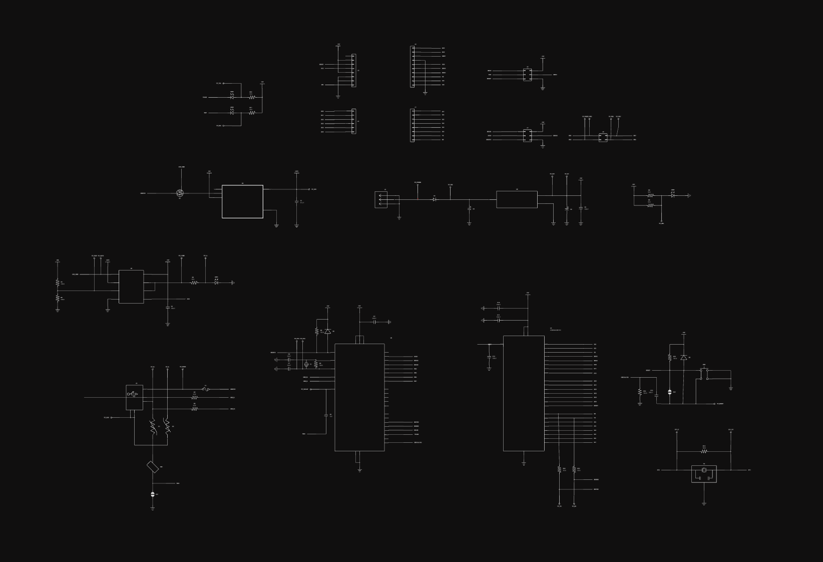
The Arduino Uno schematic consists of several components, including the microcontroller, voltage regulator, USB interface, and various other passive components. Let's take a closer look at each component and its function in the schematic.
The Arduino Uno schematic provides a comprehensive pinout that gives electrical engineers access to various peripheral interfaces, such as I2C, SPI, and PWM. To utilize these interfaces, electrical engineers must first set the appropriate pinmode using the pinmode function. This function specifies whether a pin is set to input or output, which determines its behavior. The pinout of the Arduino Uno also includes connections to the GND and 3V pins, which are used to provide power to external devices and to ground the board.
The Arduino Uno consists of a total of 20 digital pins, 6 of which can be used for PWM output, and 6 analog input pins. The pinout also includes connections to the power supply, including the GND and 3V pins, as well as a number of other peripheral interfaces, such as I2C and SPI.
Digital Pins
The digital pins on the Arduino Uno can be used for both input and output and are designated as D0 to D13. These pins can be controlled using the digitalwrite and digitalread functions in the Arduino IDE.
Analog Pins
The analog pins on the Arduino Uno are designated as A0 to A5 and can be used to read analog signals, such as those from sensors. These pins are connected to an ADC (Analog-to-Digital Converter) on the ATmega328P microcontroller, which converts the analog signal into a digital representation that can be read by the microcontroller.
PWM Pins
The Arduino Uno provides 6 PWM pins, which can be used to control analog devices, such as motors and LEDs, by adjusting the duty cycle of a pulse. These pins are designated as D3, D5, D6, D9, D10, and D11.
I2C and SPI Interfaces
The Arduino Uno pinout also includes connections to the I2C and SPI interfaces, which allow electrical engineers to communicate with other devices and peripherals, such as sensors and actuators.
Power Pins
The power pins on the Arduino Uno include the GND and 3V pins, which are used to provide power to external devices and to ground the board. The 5V pin provides a regulated 5V supply, which can be used to power external devices, while the Vin pin can be used to power the board using an external power supply.
The ATmega328P microcontroller on the Arduino Uno is programmed using the ICSP (In-Circuit Serial Programming) header. This header provides access to the MOSI, SCK, and other signals required for programming the microcontroller. The Arduino Integrated Development Environment (IDE) provides an easy-to-use interface for programming the microcontroller and uploading code to the board.
The Arduino Uno schematic provides access to 14 digital pins, which can be used to control various devices, such as LEDs and sensors. Electrical engineers can use the digitalwrite function to set the state of a digital pin to either high or low. The state of the digital pin can be read using the digitalread function, which returns a value of either 0 or 1, depending on the state of the pin.
This example Arduino code shows how to control digital pins using digitalWrite() and digitalRead() functions. In this example, we'll use a push button to control an LED. When the button is pressed, the LED will turn on; when the button is released, the LED will turn off.
This code assumes that you have a normally open push button connected to digital pin 2 and an LED connected to digital pin 13. When the button is not pressed, the internal pull-up resistor will cause the button pin to read HIGH. When the button is pressed, it will connect the pin to ground, causing the pin to read LOW.
The Arduino Uno schematic provides access to 6 PWM (Pulse Width Modulation) pins, which can be used to control analog devices, such as motors and servos. PWM allows electrical engineers to control the brightness of LEDs, the speed of motors, and other devices by adjusting the duty cycle of the pulse. This provides a more versatile and smooth control of analog devices compared to using digital signals alone.
In this example, we'll use a potentiometer to control the brightness of an LED. The potentiometer will be read using an analog input, and the LED brightness will be controlled using a PWM output.
There are several ground (GND) pins on an Arduino Uno board. Typically, you can find at least 4 GND pins located on the board's power and ground bus along the edges of the board. These pins are labeled "GND" and are used to connect components to a common ground and complete the electrical circuit.
The "0" and "1" pins on an Arduino Uno refer to the RX (Receive) and TX (Transmit) pins, respectively. These are digital pins used for serial communication with other devices, such as a computer. The RX pin is used to receive data, and the TX pin is used to transmit data. These pins can also be used for general digital input/output if serial communication is not required.
The Arduino Uno can be used in various applications, including hobby projects, IoT devices, and home automation. Engineers and hobbyists can use the schematic as a reference to create custom boards or modify existing boards to meet specific requirements. The schematic can also be used to troubleshoot issues with the board and to understand the behavior of the components.
One of the most significant advantages of using the Arduino Uno is its compatibility with the Arduino Integrated Development Environment (IDE). The Arduino IDE is a software platform that makes it easy to write, upload, and debug code for the Arduino Uno and other boards. The Arduino Uno schematic can be used in combination with the Arduino IDE to create and test new projects, making it an ideal choice for hobbyists and engineers.
The schematic of the Arduino Uno is an essential tool for electrical engineers and hobbyists to understand the behavior of the board and to modify it for specific projects.


A guide to PCB component selection, covering electrical specs, footprints, thermal performance, sourcing, and best practices for picking parts that ship reliably.
A guide to PCB design reviews, covering schematic, layout, and DFM checks engineers use to catch errors early and ship more reliable boards.

A guide to creating and managing PCB footprint libraries, covering IPC standards, pad sizing, validation workflows, and best practices for reliable land patterns.

A guide to PCB schematic best practices, covering organization, symbols, labeling, and readability tips for clean, maintainable circuit diagrams.

A guide to flexible PCB design, covering materials, stackups, bend radius, and layout best practices for wearables, medical devices, and other compact electronics.

A beginner-friendly guide to reading PCB schematics, covering common symbols, nets, and how to follow signal flow through a circuit diagram.

An overview of collaborative PCB design, showing how cloud-native tools, real-time editing, and shared libraries are reshaping modern hardware team workflows.

A guide to managing PCB component libraries, covering symbols, footprints, and 3D models with best practices for standardizing parts across hardware teams.
