September 12, 2023
LM2596 in Action: Case Study of Its Application in Power Supply Units
Share

The LM2596 is essentially a voltage regulator designed as a buck converter. It can handle input voltages up to 40V, efficiently stepping them down to produce a lower, stable output voltage (Vout) that can be as low as 3V or as high as 35V. Thanks to its FET technology, the converter can achieve excellent regulation performance.
The LM2596 is an integrated circuit (IC) designed to function as a voltage regulator in a buck converter topology. While you won't be able to see the internal components just by looking at the chip, its datasheet will reveal a variety of built-in features that facilitate voltage conversion and regulation. Here's a general breakdown of what's inside:
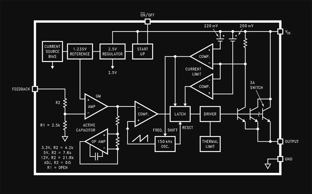
The LM2596 typically incorporates an internal power N-channel Field-Effect Transistor (FET) that acts as the switching element. This FET allows the LM2596 to switch current paths, thereby stepping down the voltage.
The internal control logic manages the timing and switching operations. It usually operates at a fixed frequency and is responsible for the opening and closing of the internal FET.
The LM2596 includes a feedback loop that measures the output voltage (Vout) and compares it to a reference voltage. Any deviation results in an error signal, which is amplified and used to adjust the duty cycle of the switching FET to keep the output voltage stable.
An internal voltage reference sets the standard against which the output voltage is compared. This is essential for the regulation process.
Some versions of the LM2596 include built-in features for thermal shutdown and current limiting to protect the IC and connected components from damage.
Although the LM2596 itself is an integrated package, its effectiveness in a buck converter circuit relies on external components like inductors, capacitors, and sometimes diodes and resistors. The IC has pins to connect these components.
The LM2596 can handle a wide range of input voltages. Whether it's a 50V input from a power converter or as low as 5V, the LM2596 ensures a reliable output.
Vin is the input voltage fed into the circuit, while Vout is the output voltage regulated by the LM2596. This makes it extremely versatile, catering to both high and low voltage requirements.
Power supply units often incorporate this DC-DC converter for its synchronous regulation capabilities. The LM2596 is capable of driving up to 5A in specific conditions, which is quite sufficient for many types of electrical loads.
Different voltage ratings like 25V, 30V, and 35V for electrolytic capacitors are often employed based on the desired output and input voltage ranges.
Voltage ripple is an essential factor to consider, and the LM2596 excels in maintaining a low ripple, thereby ensuring a stable output.

Different inductor types or core materials produce different amounts of this characteristic ringing or ripple. Ferrite coreinductors have very little core loss and therefore produce the most ringing. The higher core loss of powdered ironinductors produce less ringing. If desired, a series RC can be placed in parallel with the inductor to dampen theringing.
The LM2596 operates at a fixed frequency, aiding in easier filter design. The chip incorporates internal switching transistors, further simplifying the circuit topology.
Datasheets and Webench tools are useful resources for understanding the LM2596 circuit's pinout and diagram. Datasheets provide detailed specifications, while Webench helps in simulation and layout design for your PCB.
MOSFETs can be used in more advanced configurations to handle even higher power applications.
The synchronous buck converter version of LM2596 employs two FETs for enhanced efficiency, compared to standard buck converter topology.

The LM2596 is a versatile and robust DC-DC converter, central to many power supply systems and voltage regulator applications. Its excellent performance, including a broad voltage range of up to 50V and low ripple, make it a preferred choice. Whether you're focusing on inductor specifications, capacitor types, diode characteristics, or FET functionalities, this IC has proven itself as an efficient voltage regulator in both asynchronous and synchronous settings.
Before diving into your project, make sure to refer to datasheets for the most accurate information. Diagrams are your best friend when laying out your PCB. Remember, you can use the LM2596 in adjustable setups by modifying the resistor values to achieve custom voltage outputs.
LM2596 offers a reliable and efficient solution for all your voltage regulation needs, serving as the cornerstone in many buck converter and power converter applications.


A guide to flexible PCB design, covering materials, stackups, bend radius, and layout best practices for wearables, medical devices, and other compact electronics.

A beginner-friendly guide to reading PCB schematics, covering common symbols, nets, and how to follow signal flow through a circuit diagram.

An overview of collaborative PCB design, showing how cloud-native tools, real-time editing, and shared libraries are reshaping modern hardware team workflows.

A guide to managing PCB component libraries, covering symbols, footprints, and 3D models with best practices for standardizing parts across hardware teams.

An overview of PCB reverse engineering, explaining how engineers analyze boards, extract schematics, and use the process for legacy support, repair, and design analysis.

A practical guide to PCB silkscreen design, covering labeling best practices, common readability mistakes, and how clean silkscreens improve assembly and debugging.

An explainer on PCB version control, comparing hardware revision workflows to Git-style collaboration and showing how modern teams track design changes.
An introduction to schematic capture, explaining how engineers use symbols, nets, and connectivity to create circuit diagrams that drive PCB layout.
