
Try Flux for free
Designing and building your own custom printed circuit board (PCB) for a drone can be an exciting and educational project. With the right components and some basic skills, you can create a PCB to control motors, manage sensors, power components, and more for your drone.
Ever since you first explored the world of flight dynamics and controls, you might have dreamed of designing your own quadcopter or fixed-wing flight controller from scratch. The chance to apply knowledge of electronics, circuitry, programming, and flight controls to a real-world project is undoubtedly thrilling.
In this guide, we'll walk through the full process of creating a custom PCB of a drone flight control system step-by-step.
We'll cover:
By the end, you'll have the knowledge to design and build your own custom drone PCB for motors, controllers, cameras, and other components. Let's get started!
The first step is to plan out the electronics circuit for the drone PCB. This involves creating a schematic diagram showing the components and connections.
Here are some things to include in your schematic:
Sensor Suite
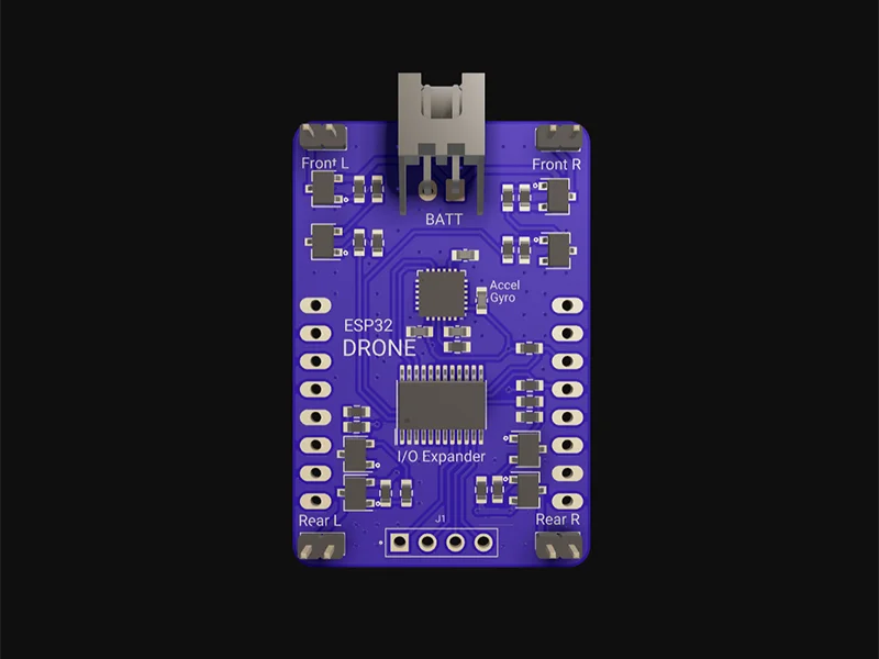
Sensors are the most important components in a flight controller. They are your system’s eyes and ears, after all. The absolute bare-minimum sensor suite to fly a drone is a gyroscope and accelerometer. The flight controller must be able to keep the drone stable and responsive to external disturbances and commands, while avoiding overshooting, oscillations, and drifts.
Every flight controller system will have an IMU, magnetometer, barometer, and GPS sensor onboard. The IMU, or inertial measurement unit, consists of an accelerometer and gyroscope. The gyro and accelerometer measurements can be fused to compute roll and pitch angles and rates.
Battery and power supply
Microcontroller
Connectors
Other components
Spend time thinking through all components needed before moving to the layout stage.
Once you have the circuit schematic, it's time to select the actual electronic components to use for the PCB. Here are some tips:
Choosing components with the right specifications prevents problems down the road. Consult datasheets and device libraries when selecting parts.
In Flux, all you have to do is create a new project and everything is ready to go! What’s more - all public projects, parts, and modules can be forked and built upon with the click of a button.
Ready to dive in?
To get inspired or see how others have built their drone projects, check out our example projects for drones. These showcase a variety of drone flight control system designs, such as those powered by stm32 down to just basic arduino. By exploring these examples, you can understand how different elements come together and even reuse parts of the design for your own project.
{{drones_projects="/p/content-library"}}
With the schematic complete and components selected, it's time to design the physical layout of the PCB. This involves carefully arranging components and routing connections on a PCB design software tool. Here are some tips for PCB layout:
Place components strategically
Create power and ground planes
Route traces efficiently
Include power and signal Decoupling
Add test points
Review design rules (DRC)
Following good layout practices results in a robust, high-quality PCB design. Take the time to optimize the board layout before moving to PCB fabrication.
Once you've designed the PCB layout, it's time to get the board physically manufactured. Here are some options for making PCBs:
Professional PCB manufacturing and assembly
Consider your design requirements, budget, and timeline when choosing the best PCB making method for your project.
Watch our in-depth video tutorials that guide you through the process of designing a flight controller PCBs, from component selection to final layout. Perfect for beginners and experts alike!
{{universal-tutorial-video="/p/content-library"}}
Join our Slack community of PCB designers, drone builders and enthusiasts. Share ideas, ask questions, and get feedback on your designs in real-time.
Access detailed articles and documentation that cover everything from basic drone first principles and techniques to troubleshooting tips.
Flux empowers you to design professional drones flight controller PCBs without the hassle. With intuitive tools, expert guidance, and a community to back you up, building your next drone project has never been easier. Try Flux for free today and start designing.