August 25, 2023
The Ultimate Guide to Electrical Connectors and Wiring Connection
Share

Wire connectors come in various types, such as wire nuts, Wago connectors, and crimp connectors. Wire nuts are simple but effective, sometimes used to splice together small AWG (American Wire Gauge) wires. The twist and insulating properties of wire nuts make them popular in residential wiring projects.
Crimping involves placing a metal conductor inside a crimp and using a crimping tool to deform the crimp, enclosing and pressing together the conductor securely. Crimped connections are durable and reliable when done correctly. Crimping is often used for electrical wire splicing and terminal applications.
In solder connectors, the conductor is soldered to ensure a robust electrical connection. While soldering requires a soldering iron and solder, the resulting connection is extremely stable and strong. These are common in PCB (Printed Circuit Board) and other high-stake electrical wiring.
Wago connectors provide a lever-action to clamp down on the wire. They are often used for stranded wire and offer a reusable solution. DC connectors are used in low-voltage applications and are color-coded for positive (RED) terminal and negative (BLACK) terminal to prevent mistakes.
Insulation is another crucial factor. The insulation around the wire should be stripped using a wire stripper to expose the conductor before using any connector. Insulated connectors provide an extra layer of safety.
The gauge wire chosen should match the requirements of the circuit and the connector. Using a wire gauge that's inappropriate can lead to overheating or inefficiency. Can sometimes lead to intermittent connection.
The American Wire Gauge (AWG) is a standard system used primarily in the United States to denote the diameter of electrically conducting wire. The current capacity of a wire varies depending on several factors, such as the insulation type, ambient temperature, and whether the wire is in free air or bundled with other wires.
This table provides a rough estimate of the current-carrying capacity of copper wires with different AWG sizes, typically used for chassis wiring.
Copper is the most common conductor material. The quality of the conductor affects the reliability of the electrical connector.
Always consider the voltage and the circuit breaker involved. Incorrectly matched connectors and circuit breakers can result in electrical fires or other hazardous conditions.
For data transmission, ethernet connectors are usually used. Junction boxes serve as receptacles for multiple wire connections. For automotive applications, DTL (Deutsch Terminal Lugs) connectors offer robustness against harsh conditions.
Electrical connectors serve as the backbone for any electrical wiring project. Whether you are splicing, crimping, or soldering, understanding the roles of each connector can make your project efficient and safe. From the humble wire nut to the complex ethernet connector, your choice of connector makes all the difference in ensuring a smooth flow of electricity through your circuit.
So, the next time you take on an electrical project, keep this guide handy to navigate through the complex yet fascinating world of electrical connectors.
Happy Wiring!


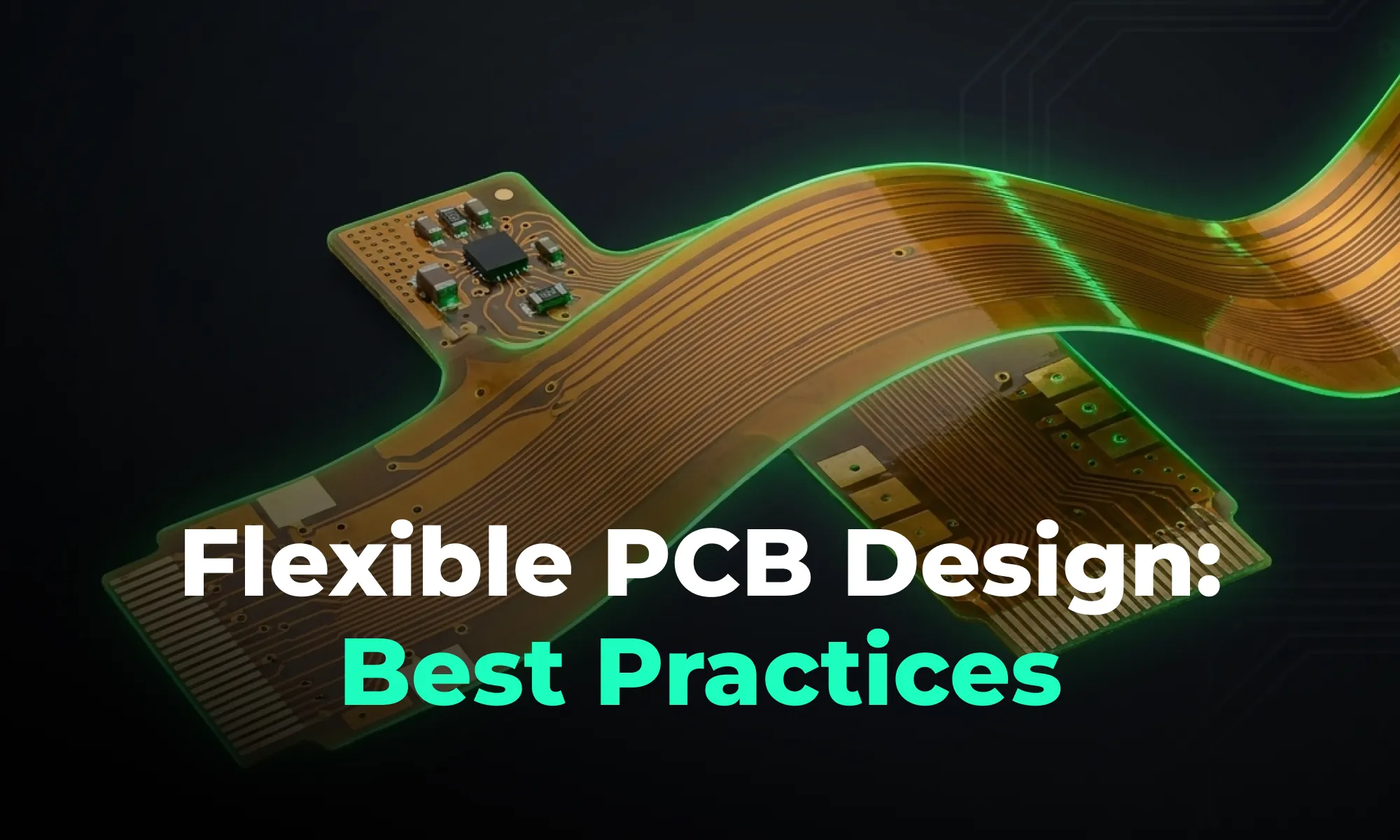
A guide to flexible PCB design, covering materials, stackups, bend radius, and layout best practices for wearables, medical devices, and other compact electronics.

A beginner-friendly guide to reading PCB schematics, covering common symbols, nets, and how to follow signal flow through a circuit diagram.

An overview of collaborative PCB design, showing how cloud-native tools, real-time editing, and shared libraries are reshaping modern hardware team workflows.

A guide to managing PCB component libraries, covering symbols, footprints, and 3D models with best practices for standardizing parts across hardware teams.

An overview of PCB reverse engineering, explaining how engineers analyze boards, extract schematics, and use the process for legacy support, repair, and design analysis.
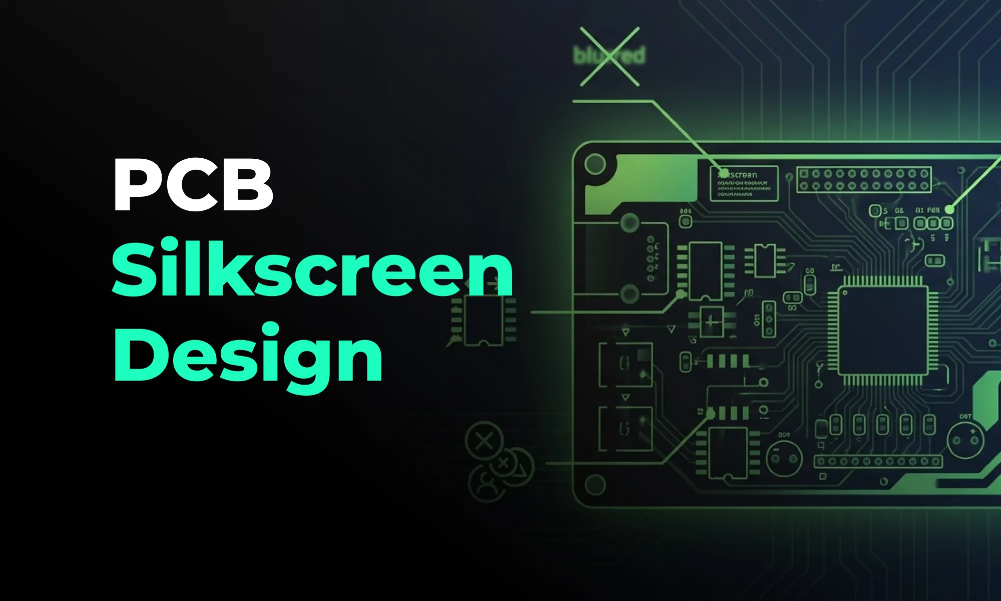
A practical guide to PCB silkscreen design, covering labeling best practices, common readability mistakes, and how clean silkscreens improve assembly and debugging.

An explainer on PCB version control, comparing hardware revision workflows to Git-style collaboration and showing how modern teams track design changes.
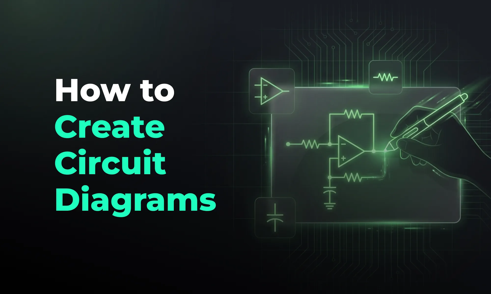
An introduction to schematic capture, explaining how engineers use symbols, nets, and connectivity to create circuit diagrams that drive PCB layout.
