Chat
Welcome to Flux
Treat Flux like your intern. Tell it what you'd like to build and it'll get to work. You can also ask it questions, brainstorm ideas, and teach it your preferences. Learn More
Explain project
Write a project description
Find schematic issues
Create a test plan
Simulate a circuit
Prepare for Manufacturing
Component Selection Workflow
New Subsystem Wizard
Write I2C initialization code
Generate firmware skeleton
adc.cpp

@copilot adc.cpp
#include <Arduino.h>

#include "adp_config.hpp"

#include "Modules/ModuleConfig.hpp"

#include "SPI.h"

#include <driver/adc.h>

#include "Modules/ModuleLights.hpp"


SPIClass* spiPot = nullptr;

static const int spiClk = 80000000; // 80 MHz

static bool spiReady = false;

adc1_channel_t channel = ADC1_CHANNEL_9;


#ifdef SENSOR_MAP_MINIPAD

uint8_t sensorLookup[16] = {

    5, // FSRioV3 input 3

    7, // FSRioV3 input 1

    8, // FSRioV3 input 16

    10, // FSRioV3 input 14

    0,

    0,

    0,

    0,

    0,

    0,

    0,

    0,

    0,

    0,

    0,

    0

};

#else

uint8_t sensorLookup[16] = {

    7, // FSRioV3 input 1

    6, // FSRioV3 input 2

    5, // FSRioV3 input 3

    4, // FSRioV3 input 4

    3, // FSRioV3 input 5

    2, // FSRioV3 input 6

    1, // FSRioV3 input 7

    0, // FSRioV3 input 8

    15, // FSRioV3 input 9

    14, // FSRioV3 input 10

    13, // FSRioV3 input 11

    12, // FSRioV3 input 12

    11, // FSRioV3 input 13

    10, // FSRioV3 input 14

    9, // FSRioV3 input 15

    8 // FSRioV3 input 16

};

#endif


void HAL_ADC_Init()

{

    adc1_config_channel_atten(channel, ADC_ATTEN_DB_12);


    spiPot = new SPIClass(HSPI);


    spiPot->begin(PIN_SPI_SCK, PIN_SPI_MISO, PIN_SPI_MOSI, PIN_SPI_POT_CS);

    spiPot->beginTransaction(SPISettings(spiClk, MSBFIRST, SPI_MODE0));


    pinMode(PIN_MUX_1, OUTPUT);

    pinMode(PIN_MUX_2, OUTPUT);

    pinMode(PIN_MUX_3, OUTPUT);

    pinMode(PIN_MUX_4, OUTPUT);

    pinMode(PIN_SPI_POT_CS, OUTPUT);


    digitalWrite(PIN_SPI_POT_CS, HIGH);


    spiReady = true;

}


void setMuxer(uint8_t sensorIndex)

{

    sensorIndex = sensorLookup[sensorIndex];


    digitalWrite(PIN_MUX_1, (bool)(sensorIndex & 0b0001));

    digitalWrite(PIN_MUX_2, (bool)(sensorIndex & 0b0010));

    digitalWrite(PIN_MUX_3, (bool)(sensorIndex & 0b0100));

    digitalWrite(PIN_MUX_4, (bool)(sensorIndex & 0b1000));

}


void setDigipot(uint8_t sensorIndex)

{

    const SensorConfig& sensorConfig = ModuleConfigInstance.GetSensorConfig(sensorIndex);


    digitalWrite(PIN_SPI_POT_CS, LOW);

    spiPot->transfer(0b00010001);

    spiPot->transfer(sensorConfig.resistorValue);

    digitalWrite(PIN_SPI_POT_CS, HIGH);

}


uint16_t HAL_ADC_ReadSensor(uint8_t sensorIndex)

{

    if(!spiReady)

        return 0;


    setMuxer(sensorIndex);

    setDigipot(sensorIndex);

    adc1_config_channel_atten(channel, ADC_ATTEN_DB_12);

    uint16_t value = adc1_get_raw(channel);


    return value;

}```


adc.h
```/*
 * SPDX-FileCopyrightText: 2015-2021 Espressif Systems (Shanghai) CO LTD
 *
 * SPDX-License-Identifier: Apache-2.0
 */

#pragma once

#include <stdint.h>
#include <stdbool.h>
#include "esp_err.h"
#include "sdkconfig.h"
#include "driver/gpio.h"
#include "hal/adc_types.h"

#ifdef __cplusplus
extern "C" {
#endif

#if CONFIG_IDF_TARGET_ESP32
/**** `adc1_channel_t` will be deprecated functions, combine into `adc_channel_t` ********/
typedef enum {
    ADC1_CHANNEL_0 = 0, /*!< ADC1 channel 0 is GPIO36 */
    ADC1_CHANNEL_1,     /*!< ADC1 channel 1 is GPIO37 */
    ADC1_CHANNEL_2,     /*!< ADC1 channel 2 is GPIO38 */
    ADC1_CHANNEL_3,     /*!< ADC1 channel 3 is GPIO39 */
    ADC1_CHANNEL_4,     /*!< ADC1 channel 4 is GPIO32 */
    ADC1_CHANNEL_5,     /*!< ADC1 channel 5 is GPIO33 */
    ADC1_CHANNEL_6,     /*!< ADC1 channel 6 is GPIO34 */
    ADC1_CHANNEL_7,     /*!< ADC1 channel 7 is GPIO35 */
    ADC1_CHANNEL_MAX,
} adc1_channel_t;
#elif CONFIG_IDF_TARGET_ESP32S2 || CONFIG_IDF_TARGET_ESP32S3 // TODO ESP32-S3 channels are wrong IDF-1776
/**** `adc1_channel_t` will be deprecated functions, combine into `adc_channel_t` ********/
typedef enum {
    ADC1_CHANNEL_0 = 0, /*!< ADC1 channel 0 is GPIO1  */
    ADC1_CHANNEL_1,     /*!< ADC1 channel 1 is GPIO2  */
    ADC1_CHANNEL_2,     /*!< ADC1 channel 2 is GPIO3  */
    ADC1_CHANNEL_3,     /*!< ADC1 channel 3 is GPIO4  */
    ADC1_CHANNEL_4,     /*!< ADC1 channel 4 is GPIO5  */
    ADC1_CHANNEL_5,     /*!< ADC1 channel 5 is GPIO6  */
    ADC1_CHANNEL_6,     /*!< ADC1 channel 6 is GPIO7  */
    ADC1_CHANNEL_7,     /*!< ADC1 channel 7 is GPIO8  */
    ADC1_CHANNEL_8,     /*!< ADC1 channel 8 is GPIO9  */
    ADC1_CHANNEL_9,     /*!< ADC1 channel 9 is GPIO10 */
    ADC1_CHANNEL_MAX,
} adc1_channel_t;
#elif CONFIG_IDF_TARGET_ESP32C3 || CONFIG_IDF_TARGET_ESP32H2
/**** `adc1_channel_t` will be deprecated functions, combine into `adc_channel_t` ********/
typedef enum {
    ADC1_CHANNEL_0 = 0, /*!< ADC1 channel 0 is GPIO0 */
    ADC1_CHANNEL_1,     /*!< ADC1 channel 1 is GPIO1 */
    ADC1_CHANNEL_2,     /*!< ADC1 channel 2 is GPIO2 */
    ADC1_CHANNEL_3,     /*!< ADC1 channel 3 is GPIO3 */
    ADC1_CHANNEL_4,     /*!< ADC1 channel 4 is GPIO4 */
    ADC1_CHANNEL_MAX,
} adc1_channel_t;
#endif // CONFIG_IDF_TARGET_*

#if CONFIG_IDF_TARGET_ESP32 || CONFIG_IDF_TARGET_ESP32S2 || CONFIG_IDF_TARGET_ESP32S3 // TODO ESP32-S3 channels are wrong IDF-1776
/**** `adc2_channel_t` will be deprecated functions, combine into `adc_channel_t` ********/
typedef enum {
    ADC2_CHANNEL_0 = 0, /*!< ADC2 channel 0 is GPIO4  (ESP32), GPIO11 (ESP32-S2) */
    ADC2_CHANNEL_1,     /*!< ADC2 channel 1 is GPIO0  (ESP32), GPIO12 (ESP32-S2) */
    ADC2_CHANNEL_2,     /*!< ADC2 channel 2 is GPIO2  (ESP32), GPIO13 (ESP32-S2) */
    ADC2_CHANNEL_3,     /*!< ADC2 channel 3 is GPIO15 (ESP32), GPIO14 (ESP32-S2) */
    ADC2_CHANNEL_4,     /*!< ADC2 channel 4 is GPIO13 (ESP32), GPIO15 (ESP32-S2) */
    ADC2_CHANNEL_5,     /*!< ADC2 channel 5 is GPIO12 (ESP32), GPIO16 (ESP32-S2) */
    ADC2_CHANNEL_6,     /*!< ADC2 channel 6 is GPIO14 (ESP32), GPIO17 (ESP32-S2) */
    ADC2_CHANNEL_7,     /*!< ADC2 channel 7 is GPIO27 (ESP32), GPIO18 (ESP32-S2) */
    ADC2_CHANNEL_8,     /*!< ADC2 channel 8 is GPIO25 (ESP32), GPIO19 (ESP32-S2) */
    ADC2_CHANNEL_9,     /*!< ADC2 channel 9 is GPIO26 (ESP32), GPIO20 (ESP32-S2) */
    ADC2_CHANNEL_MAX,
} adc2_channel_t;
#elif CONFIG_IDF_TARGET_ESP32C3 || CONFIG_IDF_TARGET_ESP32H2
/**** `adc2_channel_t` will be deprecated functions, combine into `adc_channel_t` ********/
typedef enum {
    ADC2_CHANNEL_0 = 0, /*!< ADC2 channel 0 is GPIO5 */
    ADC2_CHANNEL_MAX,
} adc2_channel_t;
#endif


/**
 * @brief ADC rtc controller attenuation option.
 *
 * @note  This definitions are only for being back-compatible
 */
#define ADC_ATTEN_0db   ADC_ATTEN_DB_0
#define ADC_ATTEN_2_5db ADC_ATTEN_DB_2_5
#define ADC_ATTEN_6db   ADC_ATTEN_DB_6
#define ADC_ATTEN_11db  ADC_ATTEN_DB_12

/**
 * The default (max) bit width of the ADC of current version. You can also get the maximum bitwidth
 * by `SOC_ADC_MAX_BITWIDTH` defined in soc_caps.h.
 */
#define ADC_WIDTH_BIT_DEFAULT   (ADC_WIDTH_MAX-1)

//this definitions are only for being back-compatible
#define ADC_WIDTH_9Bit  ADC_WIDTH_BIT_9
#define ADC_WIDTH_10Bit ADC_WIDTH_BIT_10
#define ADC_WIDTH_11Bit ADC_WIDTH_BIT_11
#define ADC_WIDTH_12Bit ADC_WIDTH_BIT_12

/**
 * @brief ADC digital controller encode option.
 *
 * @deprecated The ESP32-S2 doesn't use I2S DMA. Call ``adc_digi_output_format_t`` instead.
 */
typedef enum {
    ADC_ENCODE_12BIT,        /*!< ADC to DMA data format,          , [15:12]-channel [11:0]-12 bits ADC data */
    ADC_ENCODE_11BIT,        /*!< ADC to DMA data format, [15]-unit, [14:11]-channel [10:0]-11 bits ADC data */
    ADC_ENCODE_MAX,
} adc_i2s_encode_t;

/*---------------------------------------------------------------
                    Common setting
---------------------------------------------------------------*/

/**
 * @brief Enable ADC power
 * @deprecated Use adc_power_acquire and adc_power_release instead.
 */
void adc_power_on(void) __attribute__((deprecated));

/**
 * @brief Power off SAR ADC
 * @deprecated Use adc_power_acquire and adc_power_release instead.
 * This function will force power down for ADC.
 * This function is deprecated because forcing power ADC power off may
 * disrupt operation of other components which may be using the ADC.
 */
void adc_power_off(void) __attribute__((deprecated));

/**
 * @brief Increment the usage counter for ADC module.
 * ADC will stay powered on while the counter is greater than 0.
 * Call adc_power_release when done using the ADC.
 */
void adc_power_acquire(void);

/**
 * @brief Decrement the usage counter for ADC module.
 * ADC will stay powered on while the counter is greater than 0.
 * Call this function when done using the ADC.
 */
void adc_power_release(void);

/*---------------------------------------------------------------
                    ADC Single Read Setting
---------------------------------------------------------------*/
/**
 * @brief Get the GPIO number of a specific ADC1 channel.
 *
 * @param channel Channel to get the GPIO number
 * @param gpio_num output buffer to hold the GPIO number
 *
 * @return
 *   - ESP_OK if success
 *   - ESP_ERR_INVALID_ARG if channel not valid
 */
esp_err_t adc1_pad_get_io_num(adc1_channel_t channel, gpio_num_t *gpio_num);

/**
 * @brief Set the attenuation of a particular channel on ADC1, and configure its associated GPIO pin mux.
 *
 * The default ADC voltage is for attenuation 0 dB and listed in the table below.
 * By setting higher attenuation it is possible to read higher voltages.
 *
 * Due to ADC characteristics, most accurate results are obtained within the "suggested range"
 * shown in the following table.
 *
 *     +----------+-------------+-----------------+
 *     |          | attenuation | suggested range |
 *     |    SoC   |     (dB)    |      (mV)       |
 *     +==========+=============+=================+
 *     |          |       0     |    100 ~  950   |
 *     |          +-------------+-----------------+
 *     |          |       2.5   |    100 ~ 1250   |
 *     |   ESP32  +-------------+-----------------+
 *     |          |       6     |    150 ~ 1750   |
 *     |          +-------------+-----------------+
 *     |          |      11     |    150 ~ 2450   |
 *     +----------+-------------+-----------------+
 *     |          |       0     |      0 ~  750   |
 *     |          +-------------+-----------------+
 *     |          |       2.5   |      0 ~ 1050   |
 *     | ESP32-S2 +-------------+-----------------+
 *     |          |       6     |      0 ~ 1300   |
 *     |          +-------------+-----------------+
 *     |          |      11     |      0 ~ 2500   |
 *     +----------+-------------+-----------------+
 *
 * For maximum accuracy, use the ADC calibration APIs and measure voltages within these recommended ranges.
 *
 * @note For any given channel, this function must be called before the first time ``adc1_get_raw()`` is called for that channel.
 *
 * @note This function can be called multiple times to configure multiple
 *       ADC channels simultaneously. You may call ``adc1_get_raw()`` only after configuring a channel.
 *
 * @param channel ADC1 channel to configure
 * @param atten  Attenuation level
 *
 * @return
 *     - ESP_OK success
 *     - ESP_ERR_INVALID_ARG Parameter error
 */
esp_err_t adc1_config_channel_atten(adc1_channel_t channel, adc_atten_t atten);

/**
 * @brief Configure ADC1 capture width, meanwhile enable output invert for ADC1.
 *        The configuration is for all channels of ADC1
 * @param width_bit Bit capture width for ADC1
 *
 * @return
 *     - ESP_OK success
 *     - ESP_ERR_INVALID_ARG Parameter error
 */
esp_err_t adc1_config_width(adc_bits_width_t width_bit);

/**
 * @brief Take an ADC1 reading from a single channel.
 * @note ESP32:
 *       When the power switch of SARADC1, SARADC2, HALL sensor and AMP sensor is turned on,
 *       the input of GPIO36 and GPIO39 will be pulled down for about 80ns.
 *       When enabling power for any of these peripherals, ignore input from GPIO36 and GPIO39.
 *       Please refer to section 3.11 of 'ECO_and_Workarounds_for_Bugs_in_ESP32' for the description of this issue.
 *       As a workaround, call adc_power_acquire() in the app. This will result in higher power consumption (by ~1mA),
 *       but will remove the glitches on GPIO36 and GPIO39.
 *
 * @note Call ``adc1_config_width()`` before the first time this
 *       function is called.
 *
 * @note For any given channel, adc1_config_channel_atten(channel)
 *       must be called before the first time this function is called. Configuring
 *       a new channel does not prevent a previously configured channel from being read.
 *
 * @param  channel ADC1 channel to read
 *
 * @return
 *     - -1: Parameter error
 *     -  Other: ADC1 channel reading.
 */
int adc1_get_raw(adc1_channel_t channel);

#if CONFIG_IDF_TARGET_ESP32 || CONFIG_IDF_TARGET_ESP32S2 || CONFIG_IDF_TARGET_ESP32S3
//TODO IDF-3610, replace these with proper caps
/**
 * @brief Set ADC data invert
 * @param adc_unit ADC unit index
 * @param inv_en whether enable data invert
 * @return
 *     - ESP_OK success
 *     - ESP_ERR_INVALID_ARG Parameter error
 */
esp_err_t adc_set_data_inv(adc_unit_t adc_unit, bool inv_en);

/**
 * @brief Set ADC source clock
 * @param clk_div ADC clock divider, ADC clock is divided from APB clock
 * @return
 *     - ESP_OK success
 */
esp_err_t adc_set_clk_div(uint8_t clk_div);

/**
 * @brief Configure ADC capture width.
 *
 * @param adc_unit ADC unit index
 * @param width_bit Bit capture width for ADC unit.
 *
 * @return
 *     - ESP_OK success
 *     - ESP_ERR_INVALID_ARG Parameter error
 */
esp_err_t adc_set_data_width(adc_unit_t adc_unit, adc_bits_width_t width_bit);

/**
 * @brief Configure ADC1 to be usable by the ULP
 *
 * This function reconfigures ADC1 to be controlled by the ULP.
 * Effect of this function can be reverted using ``adc1_get_raw()`` function.
 *
 * Note that adc1_config_channel_atten, ``adc1_config_width()`` functions need
 * to be called to configure ADC1 channels, before ADC1 is used by the ULP.
 */
void adc1_ulp_enable(void);
#endif  //#if CONFIG_IDF_TARGET_ESP32 || CONFIG_IDF_TARGET_ESP32S2 || CONFIG_IDF_TARGET_ESP32S3

/**
 * @brief Get the GPIO number of a specific ADC2 channel.
 *
 * @param channel Channel to get the GPIO number
 *
 * @param gpio_num output buffer to hold the GPIO number
 *
 * @return
 *   - ESP_OK if success
 *   - ESP_ERR_INVALID_ARG if channel not valid
 */
esp_err_t adc2_pad_get_io_num(adc2_channel_t channel, gpio_num_t *gpio_num);

/**
 * @brief Configure the ADC2 channel, including setting attenuation.
 *
 * The default ADC voltage is for attenuation 0 dB and listed in the table below.
 * By setting higher attenuation it is possible to read higher voltages.
 *
 * Due to ADC characteristics, most accurate results are obtained within the "suggested range"
 * shown in the following table.
 *
 *     +----------+-------------+-----------------+
 *     |          | attenuation | suggested range |
 *     |    SoC   |     (dB)    |      (mV)       |
 *     +==========+=============+=================+
 *     |          |       0     |    100 ~  950   |
 *     |          +-------------+-----------------+
 *     |          |       2.5   |    100 ~ 1250   |
 *     |   ESP32  +-------------+-----------------+
 *     |          |       6     |    150 ~ 1750   |
 *     |          +-------------+-----------------+
 *     |          |      11     |    150 ~ 2450   |
 *     +----------+-------------+-----------------+
 *     |          |       0     |      0 ~  750   |
 *     |          +-------------+-----------------+
 *     |          |       2.5   |      0 ~ 1050   |
 *     | ESP32-S2 +-------------+-----------------+
 *     |          |       6     |      0 ~ 1300   |
 *     |          +-------------+-----------------+
 *     |          |      11     |      0 ~ 2500   |
 *     +----------+-------------+-----------------+
 *
 * For maximum accuracy, use the ADC calibration APIs and measure voltages within these recommended ranges.
 *
 * @note This function also configures the input GPIO pin mux to
 *       connect it to the ADC2 channel. It must be called before calling
 *       ``adc2_get_raw()`` for this channel.
 *
 * @note For any given channel, this function must be called before the first time ``adc2_get_raw()`` is called for that channel.
 *
 * @param channel ADC2 channel to configure
 * @param atten  Attenuation level
 *
 * @return
 *     - ESP_OK success
 *     - ESP_ERR_INVALID_ARG Parameter error
 */
esp_err_t adc2_config_channel_atten(adc2_channel_t channel, adc_atten_t atten);

/**
 * @brief Take an ADC2 reading on a single channel
 *
 * @note ESP32:
 *       When the power switch of SARADC1, SARADC2, HALL sensor and AMP sensor is turned on,
 *       the input of GPIO36 and GPIO39 will be pulled down for about 80ns.
 *       When enabling power for any of these peripherals, ignore input from GPIO36 and GPIO39.
 *       Please refer to section 3.11 of 'ECO_and_Workarounds_for_Bugs_in_ESP32' for the description of this issue.
 *       As a workaround, call adc_power_acquire() in the app. This will result in higher power consumption (by ~1mA),
 *       but will remove the glitches on GPIO36 and GPIO39.
 *
 *
 * @note ESP32:
 *       For a given channel, ``adc2_config_channel_atten()``
 *       must be called before the first time this function is called. If Wi-Fi is started via ``esp_wifi_start()``, this
 *       function will always fail with ``ESP_ERR_TIMEOUT``.
 *
 * @note ESP32-S2:
 *       ADC2 support hardware arbiter. The arbiter is to improve the use efficiency of ADC2. After the control right is robbed by the high priority,
 *       the low priority controller will read the invalid ADC2 data. Default priority: Wi-Fi > RTC > Digital;
 *
 * @param channel ADC2 channel to read
 * @param width_bit Bit capture width for ADC2
 * @param raw_out the variable to hold the output data.
 *
 * @return
 *     - ESP_OK if success
 *     - ESP_ERR_TIMEOUT ADC2 is being used by other controller and the request timed out.
 *     - ESP_ERR_INVALID_STATE The controller status is invalid. Please try again.
 */
esp_err_t adc2_get_raw(adc2_channel_t channel, adc_bits_width_t width_bit, int *raw_out);

/**
 *  @brief Output ADC1 or ADC2's reference voltage to ``adc2_channe_t``'s IO.
 *
 *  This function routes the internal reference voltage of ADCn to one of
 *  ADC2's channels. This reference voltage can then be manually measured
 *  for calibration purposes.
 *
 *  @note  ESP32 only supports output of ADC2's internal reference voltage.
 *  @param[in]  adc_unit ADC unit index
 *  @param[in]  gpio     GPIO number (Only ADC2's channels IO are supported)
 *
 *  @return
 *                  - ESP_OK: v_ref successfully routed to selected GPIO
 *                  - ESP_ERR_INVALID_ARG: Unsupported GPIO
 */
esp_err_t adc_vref_to_gpio(adc_unit_t adc_unit, gpio_num_t gpio);

/**
 *  @brief Output ADC2 reference voltage to ``adc2_channe_t``'s IO.
 *
 *  This function routes the internal reference voltage of ADCn to one of
 *  ADC2's channels. This reference voltage can then be manually measured
 *  for calibration purposes.
 *
 *  @deprecated Use ``adc_vref_to_gpio`` instead.
 *
 *  @param[in]  gpio    GPIO number (ADC2's channels are supported)
 *
 *  @return
 *                  - ESP_OK: v_ref successfully routed to selected GPIO
 *                  - ESP_ERR_INVALID_ARG: Unsupported GPIO
 */
esp_err_t adc2_vref_to_gpio(gpio_num_t gpio) __attribute__((deprecated));

/*---------------------------------------------------------------
                    DMA setting
---------------------------------------------------------------*/
/**
 * @brief Digital ADC DMA read max timeout value, it may make the ``adc_digi_read_bytes`` block forever if the OS supports
 */
#define ADC_MAX_DELAY UINT32_MAX

/**
 * @brief ADC DMA driver configuration
 */
typedef struct adc_digi_init_config_s {
    uint32_t max_store_buf_size;    ///< Max length of the converted data that driver can store before they are processed.
    uint32_t conv_num_each_intr;    ///< Bytes of data that can be converted in 1 interrupt.
    uint32_t adc1_chan_mask;        ///< Channel list of ADC1 to be initialized.
    uint32_t adc2_chan_mask;        ///< Channel list of ADC2 to be initialized.
} adc_digi_init_config_t;

/**
 * @brief ADC digital controller settings
 */
typedef struct {
    bool conv_limit_en;                      ///< To limit ADC conversion times. Conversion stops after finishing `conv_limit_num` times conversion
    uint32_t conv_limit_num;                 ///< Set the upper limit of the number of ADC conversion triggers. Range: 1 ~ 255.
    uint32_t pattern_num;                    ///< Number of ADC channels that will be used
    adc_digi_pattern_config_t *adc_pattern;    ///< List of configs for each ADC channel that will be used
    uint32_t sample_freq_hz;  /*!< The expected ADC sampling frequency in Hz. Range: 611Hz ~ 83333Hz
                                   Fs = Fd / interval / 2
                                   Fs: sampling frequency;
                                   Fd: digital controller frequency, no larger than 5M for better performance
                                   interval: interval between 2 measurement trigger signal, the smallest interval should not be smaller than the ADC measurement period, the largest interval should not be larger than 4095 */
    adc_digi_convert_mode_t conv_mode;      ///< ADC DMA conversion mode, see `adc_digi_convert_mode_t`.
    adc_digi_output_format_t format;        ///< ADC DMA conversion output format, see `adc_digi_output_format_t`.
} adc_digi_configuration_t;

/**
 * @brief Initialize the Digital ADC.
 *
 * @param init_config Pointer to Digital ADC initilization config. Refer to ``adc_digi_init_config_t``.
 *
 * @return
 *         - ESP_ERR_INVALID_ARG   If the combination of arguments is invalid.
 *         - ESP_ERR_NOT_FOUND     No free interrupt found with the specified flags
 *         - ESP_ERR_NO_MEM        If out of memory
 *         - ESP_OK                On success
 */
esp_err_t adc_digi_initialize(const adc_digi_init_config_t *init_config);

/**
 * @brief Read bytes from Digital ADC through DMA.
 *
 * @param[out] buf                 Buffer to read from ADC.
 * @param[in]  length_max          Expected length of data read from the ADC.
 * @param[out] out_length          Real length of data read from the ADC via this API.
 * @param[in]  timeout_ms          Time to wait for data via this API, in millisecond.
 *
 * @return
 *         - ESP_ERR_INVALID_STATE Driver state is invalid. Usually it means the ADC sampling rate is faster than the task processing rate.
 *         - ESP_ERR_TIMEOUT       Operation timed out
 *         - ESP_OK                On success
 */
esp_err_t adc_digi_read_bytes(uint8_t *buf, uint32_t length_max, uint32_t *out_length, uint32_t timeout_ms);

/**
 * @brief Start the Digital ADC and DMA peripherals. After this, the hardware starts working.
 *
 * @return
 *         - ESP_ERR_INVALID_STATE Driver state is invalid.
 *         - ESP_OK                On success
 */
esp_err_t adc_digi_start(void);

/**
 * @brief Stop the Digital ADC and DMA peripherals. After this, the hardware stops working.
 *
 * @return
 *         - ESP_ERR_INVALID_STATE Driver state is invalid.
 *         - ESP_OK                On success
 */
esp_err_t adc_digi_stop(void);

/**
 * @brief Deinitialize the Digital ADC.
 *
 * @return
 *         - ESP_ERR_INVALID_STATE Driver state is invalid.
 *         - ESP_OK                On success
 */
esp_err_t adc_digi_deinitialize(void);

/**
 * @brief Setting the digital controller.
 *
 * @param config Pointer to digital controller paramter. Refer to ``adc_digi_config_t``.
 *
 * @return
 *      - ESP_ERR_INVALID_STATE Driver state is invalid.
 *      - ESP_ERR_INVALID_ARG   If the combination of arguments is invalid.
 *      - ESP_OK                On success
 */
esp_err_t adc_digi_controller_configure(const adc_digi_configuration_t *config);


#if CONFIG_IDF_TARGET_ESP32S2 || CONFIG_IDF_TARGET_ESP32C3
//TODO IDF-3610
/**
 * @brief Reset adc digital controller filter.
 *
 * @param idx Filter index.
 *
 * @return
 *      - ESP_OK Success
 */
esp_err_t adc_digi_filter_reset(adc_digi_filter_idx_t idx);

/**
 * @brief Set adc digital controller filter configuration.
 *
 * @note For ESP32S2, Filter IDX0/IDX1 can only be used to filter all enabled channels of ADC1/ADC2 unit at the same time.
 *
 * @param idx Filter index.
 * @param config See ``adc_digi_filter_t``.
 *
 * @return
 *      - ESP_OK Success
 */
esp_err_t adc_digi_filter_set_config(adc_digi_filter_idx_t idx, adc_digi_filter_t *config);

/**
 * @brief Get adc digital controller filter configuration.
 *
 * @note For ESP32S2, Filter IDX0/IDX1 can only be used to filter all enabled channels of ADC1/ADC2 unit at the same time.
 *
 * @param idx Filter index.
 * @param config See ``adc_digi_filter_t``.
 *
 * @return
 *      - ESP_OK Success
 */
esp_err_t adc_digi_filter_get_config(adc_digi_filter_idx_t idx, adc_digi_filter_t *config);

/**
 * @brief Enable/disable adc digital controller filter.
 *        Filtering the ADC data to obtain smooth data at higher sampling rates.
 *
 * @note For ESP32S2, Filter IDX0/IDX1 can only be used to filter all enabled channels of ADC1/ADC2 unit at the same time.
 *
 * @param idx Filter index.
 * @param enable Enable/Disable filter.
 *
 * @return
 *      - ESP_OK Success
 */
esp_err_t adc_digi_filter_enable(adc_digi_filter_idx_t idx, bool enable);

/**
 * @brief Config monitor of adc digital controller.
 *
 * @note For ESP32S2, The monitor will monitor all the enabled channel data of the each ADC unit at the same time.
 *
 * @param idx Monitor index.
 * @param config See ``adc_digi_monitor_t``.
 *
 * @return
 *      - ESP_OK Success
 */
esp_err_t adc_digi_monitor_set_config(adc_digi_monitor_idx_t idx, adc_digi_monitor_t *config);

/**
 * @brief Enable/disable monitor of adc digital controller.
 *
 * @note For ESP32S2, The monitor will monitor all the enabled channel data of the each ADC unit at the same time.
 *
 * @param idx Monitor index.
 * @param enable True or false enable monitor.
 *
 * @return
 *      - ESP_OK Success
 */
esp_err_t adc_digi_monitor_enable(adc_digi_monitor_idx_t idx, bool enable);
#endif  //#if CONFIG_IDF_TARGET_ESP32S2 || CONFIG_IDF_TARGET_ESP32C3

#if CONFIG_IDF_TARGET_ESP32
//TODO IDF-3610
/**
 * @brief Read Hall Sensor
 *
 * @note When the power switch of SARADC1, SARADC2, HALL sensor and AMP sensor is turned on,
 *       the input of GPIO36 and GPIO39 will be pulled down for about 80ns.
 *       When enabling power for any of these peripherals, ignore input from GPIO36 and GPIO39.
 *       Please refer to section 3.11 of 'ECO_and_Workarounds_for_Bugs_in_ESP32' for the description of this issue.
 *
 * @note The Hall Sensor uses channels 0 and 3 of ADC1. Do not configure
 * these channels for use as ADC channels.
 *
 * @note The ADC1 module must be enabled by calling
 *       adc1_config_width() before calling hall_sensor_read(). ADC1
 *       should be configured for 12 bit readings, as the hall sensor
 *       readings are low values and do not cover the full range of the
 *       ADC.
 *
 * @return The hall sensor reading.
 */
int hall_sensor_read(void);

/*---------------------------------------------------------------
                    To Be Deprecated TODO: IDF-3610
---------------------------------------------------------------*/
/**
 * @brief Set I2S data source
 * @param src I2S DMA data source, I2S DMA can get data from digital signals or from ADC.
 * @return
 *     - ESP_OK success
 */
esp_err_t adc_set_i2s_data_source(adc_i2s_source_t src);

/**
 * @brief Initialize I2S ADC mode
 * @param adc_unit ADC unit index
 * @param channel ADC channel index
 * @return
 *     - ESP_OK success
 *     - ESP_ERR_INVALID_ARG Parameter error
 */
esp_err_t adc_i2s_mode_init(adc_unit_t adc_unit, adc_channel_t channel);
#endif

#ifdef __cplusplus
}
#endif````


How should I connect that mux and pot to make it work? Also explain how everything works, make a diagram with connections
1y
Sure, let's break down the ADC setup and I’ll walk you through the connections and operations.
Overview
-
Multiplexer (MUX): The multiplexer selects which sensor input to use and routes it to the ADC channel.
-
Digital Potentiometer (Digipot): The digital potentiometer is likely used to adjust the input signal or to provide a reference.
-
Pin Definitions:
PIN_MUX_1PIN_MUX_2PIN_MUX_3PIN_MUX_4
These pins control the multiplexer to select which sensor line is routed to the ADC input.
- Pin Definitions:
PIN_SPI_SCK(SPI Clock)PIN_SPI_MISO(SPI Master In Slave Out)PIN_SPI_MOSI(SPI Master Out Slave In)PIN_SPI_POT_CS(Chip Select for Potentiometer)
- Configured Channel:
adc1_channel_t channel = ADC1_CHANNEL_9
-
Initialization (
HAL_ADC_Init):- Configures ADC channel attenuation to 12 dB.
- Initializes the SPI bus for the digipot.
- Configures GPIO pins for the multiplexer and the chip select pin for the digipot.
- Sets
spiReadyflag to true.
-
Reading Sensor Value (
HAL_ADC_ReadSensor):- Checks if SPI is ready.
- Sets multiplexer to the desired sensor input based on
sensorIndex. - Sets digipot to predefined resistance settings for the selected sensor.
- Reads raw ADC value from the configured channel and returns it.
Based on the
adc.cpp provided, here is the detailed description of the connections:-
Connect Multiplexer Control Pins to GPIO pins:
- Connect
ESP32:MUX_1_PINtoMultiplexer:S1 - Connect
ESP32:MUX_2_PINtoMultiplexer:S2 - Connect
ESP32:MUX_3_PINtoMultiplexer:S3 - Connect
ESP32:MUX_4_PINtoMultiplexer:S4
- Connect
-
Connect SPI Bus to the Digital Potentiometer:
- Connect
ESP32:SPI_SCK_PINtoDigipot:SCK - Connect
ESP32:SPI_MISO_PINtoDigipot:MISO - Connect
ESP32:SPI_MOSI_PINtoDigipot:MOSI - Connect
ESP32:SPI_CS_PINtoDigipot:CS
- Connect
-
Connect Analog Input from MUX to ADC:
- Connect
Multiplexer:Z(Output) toESP32:ADC_CHANNEL_9
- Connect
How it WorksPlaintext
ESP32 Multiplexer Digipot -------- ------------- -------------- | GPIO |<--------------->| S1 | | | | PIN_MUX_1 |<--------------> S2 | | | | PIN_MUX_2 |<--------------> S3 | | | | PIN_MUX_3 |<--------------> S4 | | | | PIN_MUX_4 |<--------------> E | SCK MOSI | | | | Z (Output)|<------>| | | | ADC_CH9 |<-----------------| | MISO <-----|Digipot| | | | | CS | | SPI_SCK |------------------>| CLK | | | SPI_MISO|------------------>| D |<----------------- (SPI)| | SPI_MOSI|------------------> Digipot ---------------------- | | SPI_CS |-------------------------------------------------- |
-
Multiplexer Selection:
- The multiplexer (
setMuxer) selects one of the 16 sensor inputs based on thesensorIndex. The multiplexer control pins (PIN_MUX_1toPIN_MUX_4) are manipulated to select the appropriate input.
- The multiplexer (
-
Digital Potentiometer Configuration:
- The digipot (
setDigipot) is configured via SPI. The resistor value is set based on the sensor configuration retrieved fromModuleConfigInstance.
- The digipot (
-
ADC Reading:
- The raw analog voltage on the selected channel is read by
HAL_ADC_ReadSensorand returned as a digital value.
- The raw analog voltage on the selected channel is read by
This setup allows the ESP32 to select different sensors dynamically, adjust the potentiometer, and read analog values from the sensors using the ADC.
1y
2
How do I connect that mux and that pot to esp32?
\#define PIN\_MUX\_1 15
\#de...
1y
To connect the 74HC4067PW,118 multiplexer (mux) and the PDB181-K420K-103B potentiometer (pot) to the ESP32 according to your defined pins, follow these steps:
74HC4067PW,118 Connection:
-
Mux Address Pins (S0 to S3) to ESP32:
- Connect U3:S0 to U2:IO15
- Connect U3:S1 to U2:IO16
- Connect U3:S2 to U2:IO17
- Connect U3:S3 to U2:IO18
-
Mux Enable Pin to Ground:
- Connect U3:~E to GND (Ground)
-
Mux Z Pin (Analog Output) to ESP Analog Input Pin:
- Connect U3:Z to U2:SENSOR_VP (Analog Input, Pin 10)
-
Mux VCC to 3.3V Power:
- Connect U3:VCC to +3V3
-
Mux GND to Ground:
- Connect U3:GND to GND
-
Pot CS Pin to ESP32:
- Connect VR1:WIPER to U2:SIO14 (CS Pin, Pin 14)
-
Pot Analog Output to ESP Analog Input Pin:
- Connect VR1:CW to U2:SENSOR_VP (Analog Input, Pin 10)
-
Pot Ground to 3.3V Ground:
- Connect VR1:CCW to GND
- S0: Connect U3:S0 to U2:IO15
- S1: Connect U3:S1 to U2:IO16
- S2: Connect U3:S2 to U2:IO17
- S3: Connect U3:S3 to U2:IO18
- Z: Connect U3:Z to U2:SENSOR_VP
- VCC: Connect U3:VCC to +3V3
- GND: Connect U3:GND to GND
- WIPER: Connect VR1:WIPER to U2:CS (SIO14)
- CW: Connect VR1:CW to U2:SENSOR_VP
- CCW: Connect VR1:CCW to GND
Let me know if you need any further assistance!
1y
1
D2
CC1
CC2
USBDN
USBDN
USBDP
CC2
USBDP
VBUS
USB1
Reviews
 A generic fixed inductor suitable for rapid circuit topology development. The footprint automatically adapts based on the selected package, supporting standard SMD sizes (e.g., 0402, 0603, 0805) as well as well-known inductor packages such as SDR1806, PA4320, SRN6028, and SRR1260. Standard inductor values: 1.0 nH, 10 nH, 100 nH, 1.0 µH, 10 µH, 100 µH, 1.0 mH 1.2 nH, 12 nH, 120 nH, 1.2 µH, 12 µH, 120 µH, 1.2 mH 1.5 nH, 15 nH, 150 nH, 1.5 µH, 15 µH, 150 µH, 1.5 mH 1.8 nH, 18 nH, 180 nH, 1.8 µH, 18 µH, 180 µH, 1.8 mH 2.2 nH, 22 nH, 220 nH, 2.2 µH, 22 µH, 220 µH, 2.2 mH 2.7 nH, 27 nH, 270 nH, 2.7 µH, 27 µH, 270 µH, 2.7 mH 3.3 nH, 33 nH, 330 nH, 3.3 µH, 33 µH, 330 µH, 3.3 mH 3.9 nH, 39 nH, 390 nH, 3.9 µH, 39 µH, 390 µH, 3.9 mH 4.7 nH, 47 nH, 470 nH, 4.7 µH, 47 µH, 470 µH, 4.7 mH 5.6 nH, 56 nH, 560 nH, 5.6 µH, 56 µH, 560 µH, 5.6 mH 6.8 nH, 68 nH, 680 nH, 6.8 µH, 68 µH, 680 µH, 6.8 mH 8.2 nH, 82 nH, 820 nH, 8.2 µH, 82 µH, 820 µH, 8.2 mH #generics #CommonPartsLibraryjharwinbarrozo16.6k
- A generic fixed capacitor ideal for rapid circuit topology development. You can choose between polarized and non-polarized types, its symbol and the footprint will automatically adapt based on your selection. Supported options include standard SMD sizes for ceramic capacitors (e.g., 0402, 0603, 0805), SMD sizes for aluminum electrolytic capacitors, and through-hole footprints for polarized capacitors. Save precious design time by seamlessly add more information to this part (value, footprint, etc.) as it becomes available. Standard capacitor values: 1.0pF, 10pF, 100pF, 1000pF, 0.01uF, 0.1uF, 1.0uF, 10uF, 100uF, 1000uF, 10000uF 1.1pF, 11pF, 110pF, 1100pF 1.2pF, 12pF, 120pF, 1200pF 1.3pF, 13pF, 130pF, 1300pF 1.5pF, 15pF, 150pF, 1500pF, 0.015uF, 0.15uF, 1.5uF, 15uF, 150uF, 1500uF 1.6pF, 16pF, 160pF, 1600pF 1.8pF, 18pF, 180pF, 1800pF 2.0pF, 20pF, 200pF, 2000pF 2.2pF, 22pF, 220pF, 2200pF, 0.022uF, 0.22uF, 2.2uF, 22uF, 220uF, 2200uF 2.4pF, 24pF, 240pF, 2400pF 2.7pF, 27pF, 270pF, 2700pF 3.0pF, 30pF, 300pF, 3000pF 3.3pF, 33pF, 330pF, 3300pF, 0.033uF, 0.33uF, 3.3uF, 33uF, 330uF, 3300uF 3.6pF, 36pF, 360pF, 3600pF 3.9pF, 39pF, 390pF, 3900pF 4.3pF, 43pF, 430pF, 4300pF 4.7pF, 47pF, 470pF, 4700pF, 0.047uF, 0.47uF, 4.7uF, 47uF, 470uF, 4700uF 5.1pF, 51pF, 510pF, 5100pF 5.6pF, 56pF, 560pF, 5600pF 6.2pF, 62pF, 620pF, 6200pF 6.8pF, 68pF, 680pF, 6800pF, 0.068uF, 0.68uF, 6.8uF, 68uF, 680uF, 6800uF 7.5pF, 75pF, 750pF, 7500pF 8.2pF, 82pF, 820pF, 8200pF 9.1pF, 91pF, 910pF, 9100pF #generics #CommonPartsLibraryjharwinbarrozo1.5M
- A generic fixed resistor ideal for rapid circuit topology development. Its footprint automatically adapts based on the selected package case code—supporting 0402, 0603, 0805, 1203, and many other standard SMD packages, as well as axial horizontal and vertical configurations. Save precious design time by seamlessly add more information to this part (value, footprint, etc.) as it becomes available. Standard resistor values: 1.0 ohm, 10 ohm, 100 ohm, 1.0k ohm, 10k ohm, 100k ohm, 1.0M ohm 1.1 ohm, 11 ohm, 110 ohm, 1.1k ohm, 11k ohm, 110k ohm, 1.1M ohm 1.2 ohm, 12 ohm, 120 ohm, 1.2k ohm, 12k ohm, 120k ohm, 1.2M ohm 1.3 ohm, 13 ohm, 130 ohm, 1.3k ohm, 13k ohm, 130k ohm, 1.3M ohm 1.5 ohm, 15 ohm, 150 ohm, 1.5k ohm, 15k ohm, 150k ohm, 1.5M ohm 1.6 ohm, 16 ohm, 160 ohm, 1.6k ohm, 16k ohm, 160k ohm, 1.6M ohm 1.8 ohm, 18 ohm, 180 ohm, 1.8K ohm, 18k ohm, 180k ohm, 1.8M ohm 2.0 ohm, 20 ohm, 200 ohm, 2.0k ohm, 20k ohm, 200k ohm, 2.0M ohm 2.2 ohm, 22 ohm, 220 ohm, 2.2k ohm, 22k ohm, 220k ohm, 2.2M ohm 2.4 ohm, 24 ohm, 240 ohm, 2.4k ohm, 24k ohm, 240k ohm, 2.4M ohm 2.7 ohm, 27 ohm, 270 ohm, 2.7k ohm, 27k ohm, 270k ohm, 2.7M ohm 3.0 ohm, 30 ohm, 300 ohm, 3.0K ohm, 30K ohm, 300K ohm, 3.0M ohm 3.3 ohm, 33 ohm, 330 ohm, 3.3k ohm, 33k ohm, 330k ohm, 3.3M ohm 3.6 ohm, 36 ohm, 360 ohm, 3.6k ohm, 36k ohm, 360k ohm, 3.6M ohm 3.9 ohm, 39 ohm, 390 ohm, 3.9k ohm, 39k ohm, 390k ohm, 3.9M ohm 4.3 ohm, 43 ohm, 430 ohm, 4.3k ohm, 43K ohm, 430K ohm, 4.3M ohm 4.7 ohm, 47 ohm, 470 ohm, 4.7k ohm, 47k ohm, 470k ohm, 4.7M ohm 5.1 ohm, 51 ohm, 510 ohm, 5.1k ohm, 51k ohm, 510k ohm, 5.1M ohm 5.6 ohm, 56 ohm, 560 ohm, 5.6k ohm, 56k ohm, 560k ohm, 5.6M ohm 6.2 ohm, 62 ohm, 620 ohm, 6.2k ohm, 62K ohm, 620K ohm, 6.2M ohm 6.8 ohm, 68 ohm, 680 ohm, 6.8k ohm, 68k ohm, 680k ohm, 6.8M ohm 7.5 ohm, 75 ohm, 750 ohm, 7.5k ohm, 75k ohm, 750k ohm, 7.5M ohm 8.2 ohm, 82 ohm, 820 ohm, 8.2k ohm, 82k ohm, 820k ohm, 8.2M ohm 9.1 ohm, 91 ohm, 910 ohm, 9.1k ohm, 91k ohm, 910k ohm, 9.1M ohm #generics #CommonPartsLibraryjharwinbarrozo1.5M
- An electrical connector acting as reusable interface to a conductor and creating a point where external circuits can be connected.Terminal
- Wirelessly connects nets on schematic. Used to organize schematics and separate functional blocks. To wirelessly connect net portals, give them same designator. #portaljharwinbarrozo43.0M
- General Purpose Thick Film Standard Power and High-Power Chip Resistor 47 kOhms ±5% 0.125W, 1/8W Chip Resistor 0805 (2012 Metric) Automotive AEC-Q200 Thick Film Features: - RMCF – standard power ratings - RMCP – high power ratings - Nickel barrier terminations standard - Power derating from 100% at 70ºC to zero at +155ºC - RoHS compliant, REACH compliant, and halogen free - AEC-Q200 compliantjharwinbarrozo1.2M
- 10 µF 16 V Aluminum - Polymer Capacitors Radial, Can - SMD 30mOhm 2000 Hrs @ 105°C #commonpartslibrary #capacitor #aluminumpolymer #radialcanjharwinbarrozo1.2M
- Battery Holder (Open) Coin, 20.0mm 1 Cell SMD (SMT) Tab bate or batt #forLedBlinkjharwinbarrozo700.5k


ESP32-WROOM-32E Reference Design nJ5k
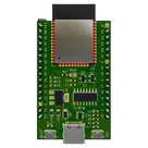
This project is a reference design for an ESP32-WROOM-32E based device. It features USB-C for power and data transfer, onboard voltage regulation, and multiple peripheral connections. It also includes a CH340C for USB to serial conversion #referenceDesign #project #ESP32 #ESP32WROOM #RF #WIFI #MCU #referenceDesign #simple-embedded #espressif #template #reference-design
Properties
Pricing & Availability
Distributor | Qty 1 |
|---|---|
Arrow | $0.95–$1.96 |
Digi-Key | $2.55–$12.50 |
LCSC | $7.85–$8.59 |
Mouser | $4.16 |
Verical | $0.96–$2.59 |
Controls
Welcome 👋
Flux helps you build PCBs faster with an AI teammate!
Create your account to collaborate, stay updated, fork your own version, and get instant answers from our AI agent.
sprzedajniok
copilot
adc.cppfile you provided.- MUX (Multiplexer)
- Potentiometer (VR1)
- ESP32
- GPIO pins for MUX control
Connections:PIN_MUX_1,PIN_MUX_2,PIN_MUX_3, andPIN_MUX_4.setMuxerfunction sets these pins based on thesensorIndexvalue fromsensorLookup.-
Potentiometer (VR1):
- One end of the potentiometer to GND.
- The other end to +3.3V.
- The wiper (middle pin) to one of the ADC input channels of the ESP32. Ensure that you configure this channel in your code (e.g.,
-
MUX Data Pin:
- The output of the MUX is connected to one of the ADC input channels on the ESP32. Assuming
Connection Diagram: Example GPIO Configuration: Summary of Connections:ADC1_CHANNEL_9).ADC1_CHANNEL_9for this example.PIN_MUX_1(Control pin) connect toMUX_CONTROL_1on MUX.PIN_MUX_2(Control pin) connect toMUX_CONTROL_2on MUX.PIN_MUX_3(Control pin) connect toMUX_CONTROL_3on MUX.PIN_MUX_4(Control pin) connect toMUX_CONTROL_4on MUX.ADC_INPUT_CHANNELon ESP32.ADC_INPUT_CHANNELon ESP32.