Top User Projects
Explore innovation and practical design in Flux.ai's top user projects. This collection highlights outstanding printed circuit board (PCB) projects crafted by our community members. Featuring a range of complexities and applications, these projects showcase the real-world potential and diversity of PCB design. The top user projects section is an invaluable resource for inspiration and learning. Whether you’re a veteran PCB designer seeking fresh ideas or a newcomer aiming to understand various design strategies, these projects offer a wealth of knowledge and insight into the dynamic world of PCB design. By highlighting the achievements of our community, the top user projects stand as a testament to the innovative spirit and collaborative nature of Flux.ai’s users, fostering a culture of knowledge sharing and continuous advancement in the field of electronics design.

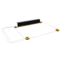
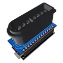
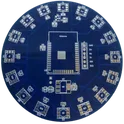
SNES Controller Arduino Nano Shield
Meet the Super Nintendo (SNES) controller port Arduino Nano Shield. This shield is fully equipped to support all types of SNES accessory inputs, like controllers, mice, and multitaps. PURCHASE_CONNECTOR: https://www.aliexpress.us/item/2251832642454072.html CODE: https://github.com/RobertDaleSmith/SNESpad
41 Uses14 Stars
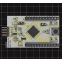
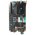
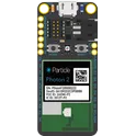
Particle Photon 2
The Photon 2 is a development module with a microcontroller and Wi-Fi networking. The form-factor is similar to the Argon (Adafruit Feather), but the Photon 2 supports 2.4 GHz and 5 GHz Wi-Fi, BLE, and has much larger RAM and flash that can support larger applications. #CommonPartsLibrary #RFEvaluation #DevelopmentBoards #Iot
88 Uses14 Stars