Part Specification Review
1:44
Analyzing the PCB layout.
Analyzing the schematic.
Looking for "Identify the official manufacturer, manufacturer part number, package name, package code, pin count / number of leads, and short product description for IMLT65R015M2HXTMA1." in 123456456789Aa
Looking for "Extract the pinout / terminal table for IMLT65R015M2HXTMA1, including each pin number, pin name, and function/description." in 123456456789Aa
Looking for "Summarize the key electrical specs for IMLT65R015M2HXTMA1: MOSFET type, VDS rating, continuous drain current, pulsed current if listed, RDS(on), power dissipation, gate charge, package, and any notable thermal or technology notes." in 123456456789Aa
Flagging package details.
Looking for "For package PG-HDSOP-16 of IMLT65R015M2HXTMA1, does the datasheet show an exposed drain tab or leadframe pad in addition to pins 9-16? Summarize the package pin naming and any footprint/land pattern notes relevant to whether a separate drain tab pad should exist in the footprint." in 123456456789Aa
Noting package properties.
- A datasheet URL is already set in the project properties, so no web search or property update was needed.
- The symbol pin mapping is mostly consistent with the datasheet.
- The main issue I found is a likely footprint mismatch: the datasheet indicates a separate central drain tab land in addition to pins 9-16, but the current footprint appears to contain only 16 pads.
Project vs datasheet summary
| Field | In project | From datasheet | Status |
|---|---|---|---|
| MPN | IMLT65R015M2HXTMA1 | IMLT65R015M2HXTMA1 | OK |
| Manufacturer | Infineon | Infineon Technologies | OK |
| Description | N-Channel 650 V 142 A 600 W Surface Mount PG-HDSOP-16-6 | SiC MOSFET, single N-channel, 650 V, 142 A, CoolSiC G2, PG-HDSOP-16 | Mostly OK |
| Mount | Surface Mount | Surface Mount | OK |
| Package naming | Not a dedicated package property in current metadata | PG-HDSOP-16 / HDSOP | Minor cleanup opportunity |
| Pin count | Implied by symbol/footprint | 16 leads | OK |
Key specs from the datasheet
| Parameter | Value |
|---|---|
| Device type | Silicon carbide MOSFET, single N-channel |
| Series | CoolSiC G2 |
| VDS | 650 V |
| Continuous drain current | 142 A at TC = 25 C |
| Continuous drain current | 101 A at TC = 100 C |
| Pulsed drain current | 398 A |
| RDS(on), typ | 14.5 mOhm at VGS = 18 V, 25 C |
| Power dissipation | 600 W at TC = 25 C |
| Total gate charge Qg | 79 nC typ |
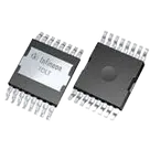
| Package | PG-HDSOP-16 |
| Notable note | Drain is pins 9-16 plus tab |
Datasheet pin functions
| Datasheet pins | Function | Current symbol terminals |
|---|---|---|
| 1-6 | Power Source | POWER_SOURCE_1, POWER_SOURCE_2, POWER_SOURCE_3, POWER_SOURCE_4, POWER_SOURCE_5, POWER_SOURCE_6 |
| 7 | Driver Source | DRIVER_SOURCE |
| 8 | Gate | GATE |
| 9-16 | Drain | DRAIN_1, DRAIN_2, DRAIN_3, DRAIN_4, DRAIN_5, DRAIN_6, DRAIN_7, DRAIN_8 |
- Pin count and numbering match the datasheet's 16-lead assignment.
- Functional naming matches the datasheet well:
- pins 1-6 as Power Source
- pin 7 as Driver Source
- pin 8 as Gate
- pins 9-16 as Drain
- The symbol is electrically organized correctly for a Kelvin-source MOSFET.
- All current terminals have Pin Type = Unspecified. That is not a datasheet mismatch, but it is incomplete metadata.
- I do not see datasheet-style per-pin descriptions stored as properties on the terminals. The names are good, but the descriptive metadata is sparse.
- The layout contains:
- a Footprint node
- 16 pad nodes corresponding to the 16 symbol terminals
- The datasheet package information says:
- Drain = pins 9-16, Tab
- The footprint / land pattern notes describe:
- 16 outer pads
- plus a large central rectangular copper area under the package
- That means the package expects a separate drain tab land in the PCB footprint.
- Likely mismatch: the current footprint appears to have only the 16 named pads, with no separate central drain tab pad visible.
- If that is correct, the footprint is incomplete relative to the datasheet land pattern.
Mismatches and flags
| Area | Finding | Severity |
|---|---|---|
| MPN | Matches datasheet | OK |
| Manufacturer | Matches datasheet | OK |
| Symbol pin count | 16 matches datasheet | OK |
| Symbol pin naming | Matches datasheet functional grouping | OK |
| Terminal metadata | Pin types are all Unspecified | Minor |
| Pin descriptions | Not fully populated from datasheet | Minor |
| Footprint | Missing explicit central drain tab pad compared with datasheet land pattern | Major |
| Package naming consistency | Project description says PG-HDSOP-16-6, datasheet extraction says PG-HDSOP-16 | Minor |
-
Fix the footprint first
- Add the central drain tab pad if it is truly missing.
- Ensure it is electrically tied to the Drain.
-
Improve terminal metadata
- Set terminal pin types and descriptions for:
- POWER_SOURCE_1 through POWER_SOURCE_6
- DRIVER_SOURCE
- GATE
- DRAIN_1 through DRAIN_8
- Set terminal pin types and descriptions for:
-
Normalize package metadata
- Add or align the package field to the exact datasheet naming you want to use consistently.


Welcome 👋
Flux accelerates your PCB design with AI.
Create your account to start using this component and bring your ideas to life.
