Downloading Model Assistance

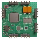
Image
Thought
I’ll add this provided board photo as a stable project asset and update the README image section to use it.
Worked
Done — I added the provided board photo as a project asset and updated the README to reference the stable local asset path.
Can you fix the formatting on page Betaflight Firmware?
Thought
I’ll clean up the Betaflight Firmware document formatting while preserving its content, then verify the result.
Worked
Done — I cleaned up the Betaflight Firmware page with proper Markdown headings, bullet lists, numbered setup steps, a fenced CLI code block, and a safety/bring-up checklist.
Review firmware mapping
Fix README images
Run project review
Check BOM accuracy
Export manufacturing files
Refine this doc
Ask about this doc
README
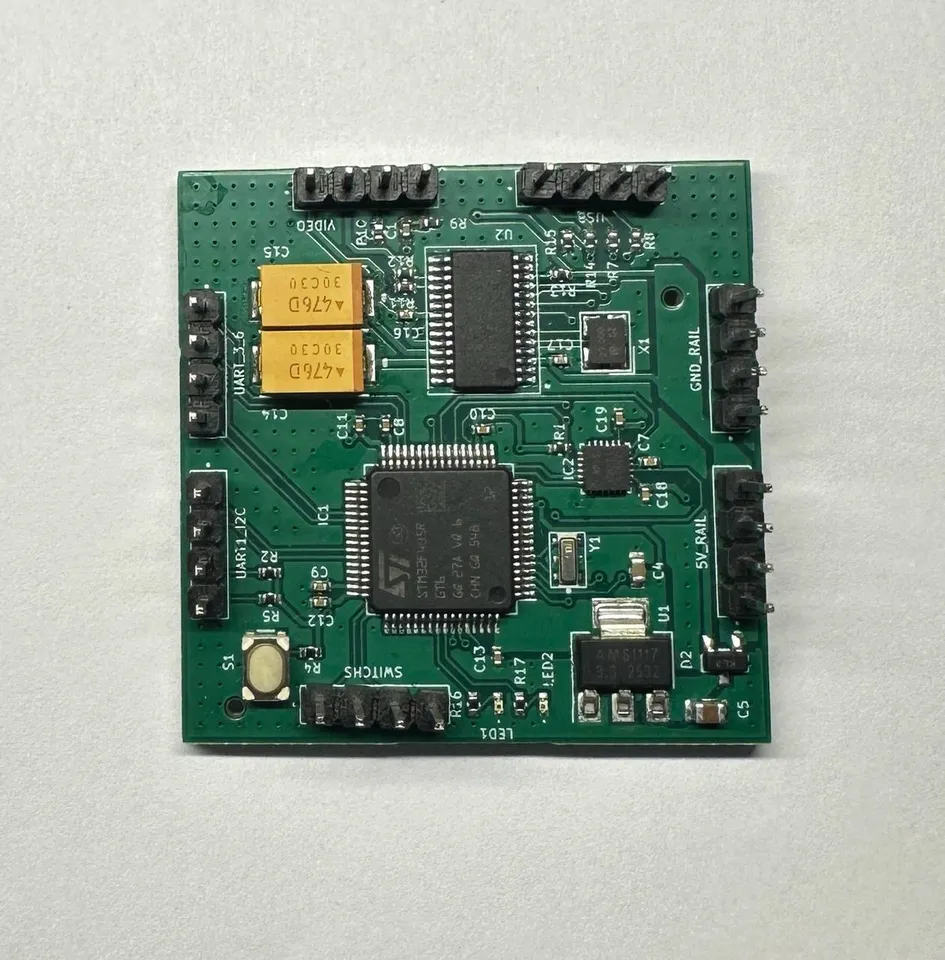
STM32F4 Flight Controller
Сompact template of the STM32F4 flight controller, modular platform designed for rapid prototyping of quadcopters and experiments with sensors and flight algorithms.
Image
Inspiration & Idea
I was inspired by projects like this glove-controlled drone (https://www.hackster.io/news/building-a-glove-controlled-drone-8faecd3fe50b) and wanted to build a platform that lets me implement whatever control logic I imagine — simple commands (forward, left, right) or advanced autonomous behaviors. I therefore built a flight controller on the STM32F405RGT6 and a companion ESC to give me full hardware control — a compact, configurable base ready for adding AI-based object detection and tracking.
Complementary ESC project: readme
DroneImage
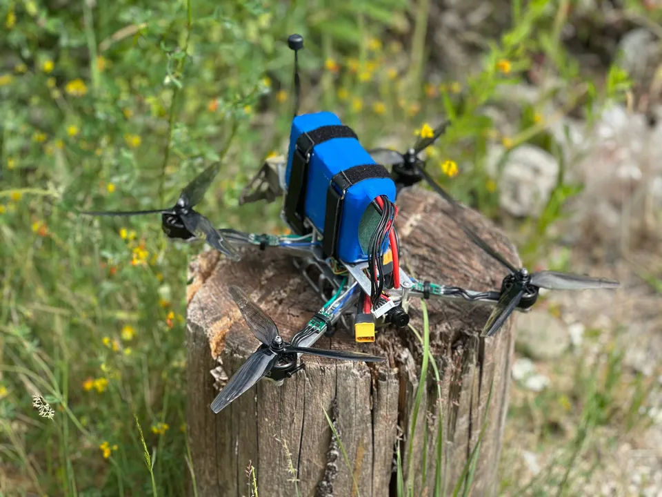
You can view the drone's build here - skeleton-and-muscles-of-a-quadcopter
Board Specs
The design includes the core subsystems typically needed in a multirotor controller:
- MCU: STM32F405RGT6 (Cortex-M4, FPU)
- Input voltage: VIN 5V (on-board regulators for 5V/3.3V)
- On-board sensors: IMU (SPI/I2C) support; no barometer included
- Sensor interfaces: SPI, I2C, I2S (for IMU/compass/other)
- Motor outputs: 4–8 PWM / DShot-capable outputs (ESC control)
- Communication: UART (telemetry/config), USB (DFU/serial), CAN optional
- Firmware: modular structure (drivers, sensors, control, comms), RTOS-ready (FreeRTOS compatible)
- Telemetry: supports DShot telemetry / UART telemetry to GCS
- Protections: failsafe, arming checks, sensor calibration routines
- Expandability: external barometer/GPS/camera/AI module via UART/I2C/SPI/USB
- Documentation: schematic, BOM, configuration files, and flash/build instructions (link to files to be added)
- Complementary ESC project: readme
Flight Through Failures
Warning: Always remove propellers before adjusting hardware or firmware!!!
Overview
I started as an experiment — I wanted a working platform to quickly develop flight logic, so I soldered a controller based on the STM32F405RGT6 and simultaneously designed my own ESC to have full control over the hardware. The modular firmware architecture let me work in parallel on drivers, sensors, and motor control.
You can find out why I chose this particular STM32 here - why-the-stm32f405rgt6

Image
Hardware Challenges
The hardest issues were hardware-related: routing pins for all interfaces without conflicts, eliminating motor-induced power noise with a VIN = 5V supply, and thermal/current problems on the ESC under load. Electromagnetic interference from motors affected the IMU, so I tested filters, shielding, and sensor placement. The OSD chip initially failed because it was on “slow” MCU pins — I solved it by lowering the SPI clock for that interface (or by remapping the OSD to a faster pin).
Firmware & Calibration
Firmware work required synchronizing PWM/DShot, calibrating the IMU and magnetometer correctly, and implementing failsafe and arming procedures. These features needed extensive bench testing before mounting propellers.
I documented the main Betaflight settings in the betaflight-firmware
Test Flights
I conducted many test flights, including several flyaways caused by unsynchronized motors, which forced improvements to motor timing, ESC calibration, and safety logic. ESC testing also highlighted the need for additional over-current protection and more accurate shunt measurement.

Current Status & Next Steps
The platform now flies and enables rapid prototyping of movement logic, but achieving stability required many small fixes, schematic revisions, and fine-tuning. Next I plan to integrate AI modules for object detection and tracking and address the identified hardware/software improvements first.
Building It Yourself
If you want to build your own flight controller, you can order the PCB from a fab like JLCPCB or fork the project and adapt it to your needs. You’ll also need the firmware source—update pin mappings/resources and rebuild (STM32 toolchain/STM32CubeIDE or Makefile).
Recommended steps:
- Review and update the BOM for available parts and suitable substitutes.
- Adjust PCB layout/pin mapping if you need different connectors, sensors
- Order prototypes (small batch) from JLCPCB or a similar service.
- Populate power rails and regulators first; verify voltages before installing the MCU.
- Flash minimal firmware, fix resource conflicts, then add sensors and ESC connections.
- Perform bench tests (props off), calibrate IMU/magnetometer, apply Betaflight settings, and only then do flight tests.
Like Edison, who turned thousands of attempts into the light bulb, persistence wins. Keep experimenting, and you will succeed!
README
STM32F4 Flight Controller
Inspiration & Idea
Board Specs
Flight Through Failures
Overview
Hardware Challenges
Firmware & Calibration
Test Flights
Current Status & Next Steps
Building It Yourself