Downloading Model Assistance


Image
Thought
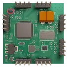
I’ll add this provided board photo as a stable project asset and update the README image section to use it.
Worked
Done — I added the provided board photo as a project asset and updated the README to reference the stable local asset path.
Can you fix the formatting on page Betaflight Firmware?
Thought
I’ll clean up the Betaflight Firmware document formatting while preserving its content, then verify the result.
Worked
Done — I cleaned up the Betaflight Firmware page with proper Markdown headings, bullet lists, numbered setup steps, a fenced CLI code block, and a safety/bring-up checklist.
Review firmware mapping
Fix README images
Run project review
Check BOM accuracy
Export manufacturing files
Refine this doc
Ask about this doc
Betaflight Firmware
Complete Betaflight configuration and setup guide for the STM32F401CCU6-based flight controller PCB.

Betaflight Configuration
This flight controller is intended to be compatible with Betaflight firmware and includes a resource mapping for the onboard peripherals.
Note: Verify the exact MCU target and pin mapping against the schematic before flashing or flying.
Recommended Target

Image
Board: AIRB/OMNIBUSF4SD(STM32F405). This target provides optimal compatibility with the STM32F4 architecture and includes support for all integrated peripherals including SD card functionality.
CLI Resource Configuration
Copy and paste the following resource mapping into the Betaflight CLI, then run
save.Text
# STM32F4 Flight Controller Resource Mapping resource BEEPER 1 B04 resource MOTOR 1 B00 resource MOTOR 2 B01 resource MOTOR 3 C06 resource MOTOR 4 C07 resource MOTOR 5 A01 resource MOTOR 6 A08 resource LED_STRIP 1 B06 resource SERIAL_TX 1 A09 resource SERIAL_TX 3 B10 resource SERIAL_RX 1 A10 resource SERIAL_RX 3 B11 resource INVERTER 3 C09 resource INVERTER 6 C08 resource LED 1 B05 resource SPI_SCK 1 A05 resource SPI_SCK 2 B13 resource SPI_SCK 3 C10 resource SPI_SDI 1 A06 resource SPI_SDI 2 B14 resource SPI_SDI 3 C11 resource SPI_SDO 1 A07 resource SPI_SDO 2 B15 resource SPI_SDO 3 C12 resource ADC_BATT 1 C02 resource ADC_RSSI 1 A00 resource ADC_CURR 1 C01 resource BARO_CS 1 B03 resource SDCARD_CS 1 B12 resource SDCARD_DETECT 1 B07 resource OSD_CS 1 A15 resource GYRO_EXTI 1 C04 resource GYRO_CS 1 A04 resource USB_DETECT 1 C05 save
Hardware Feature Mapping

Image
Motor Outputs
- MOTOR 1-4: Primary quadcopter motor outputs:
B00,B01,C06,C07 - MOTOR 5-6: Additional outputs for hex/octo configurations:
A01,A08 - Supported protocols may include DShot, Multishot, and standard PWM depending on firmware target and timer support.
Sensor Configuration
- Gyroscope / Accelerometer: MPU6050/MPU-6000-class IMU on SPI1
- CS:
A04 - EXTI:
C04
- CS:
- Barometer: MS5611 on SPI1
- CS:
B03
- CS:
- OSD: MAX7456 on SPI2
- CS:
A15
- CS:
- SD Card / Blackbox Logging
- CS:
B12 - Detect:
B07
- CS:
UART Mapping
- UART1: GPS or MSP
- TX:
A09 - RX:
A10
- TX:
- UART3: SBUS / telemetry with inverter
- TX:
B10 - RX:
B11
- TX:
- Inverters:
- UART3 inverter:
C09 - UART6 inverter:
C08
- UART3 inverter:
Analog Inputs
- Battery voltage:
C02/ADC_BATT - Current sensor:
C01/ADC_CURR - RSSI:
A00/ADC_RSSI
Initial Setup Steps
1. Flash Betaflight Firmware
- Connect the flight controller via USB.
- Open Betaflight Configurator.
- Go to the Firmware Flasher tab.
- Select the appropriate STM32F4 target for this board.
- Choose the latest stable firmware.
- Enable Full Chip Erase.
- Flash the firmware.
2. Apply Resource Configuration
- Connect to the flight controller in Betaflight Configurator.
- Open the CLI tab.
- Paste the resource configuration from this document.
- Type
saveand press Enter. - Wait for the controller to reboot.
3. Sensor Calibration
- Place the board flat and keep it still.
- Go to the Setup tab.
- Click Calibrate Accelerometer.
- Let the gyroscope auto-calibrate on startup while the board remains still.
Bring-Up Checklist
Before connecting motors or propellers:
- Confirm the board powers up correctly from USB.
- Confirm the 5V rail is stable.
- Confirm Betaflight connects over USB.
- Confirm the accelerometer and gyroscope move in the correct directions.
- Confirm UART ports are assigned correctly.
- Confirm motor output order without propellers installed.
- Confirm receiver input and failsafe behavior.
- Confirm OSD output before flight use.
Safety Note
Always test without propellers installed until firmware configuration, motor direction, receiver mapping, and failsafe behavior are confirmed.
Betaflight Firmware
Betaflight Configuration
Recommended Target
CLI Resource Configuration
Hardware Feature Mapping
Motor Outputs
Sensor Configuration
UART Mapping
Analog Inputs
Initial Setup Steps
1. Flash Betaflight Firmware
2. Apply Resource Configuration
3. Sensor Calibration
Bring-Up Checklist
Safety Note