Adding CAN Network with MCP2515
Thought for 51 sec
130 days
Automotive TVS options ahead of the regulator
Recommendation
Placement
Table
| Part | Package | Manufacturer | Why it stands out |
|---|---|---|---|
| SMCJ24A-Q | SMC | Bourns | Best balanced choice for the 12 V input ahead of IC1 |
| SM8S24A-Q | DO-218 | Bourns | Heavier-duty option if you want more surge margin at the 39514-5004 entry |
| SMBJ28A-Q | SMB | Bourns | Smaller package option if space matters more than surge robustness |
| SMBJ26A-Q | SMB | Bourns | Similar compact automotive option |
| SMCJ24AQ-13-F | SMC | Diodes | Reasonable alternative to the Bourns SMC part |
- Put the TVS directly behind the 39514-5004, from +12 V to GND, before the input path feeding IC1.
If you want, I can next find a matching reverse-polarity protection part for the same input path.
Find reverse protection
Smaller TVS options
Check regulator input
Review input path
What are the pads SBU1 SBU2 for?

2y
The pads "SBU1" and "SBU2" are associated with the USB-C connector in your project (Designator: J1). These pads represent the Sideband Use (SBU) lines in the USB Type-C interface.
SBU lines are additional data lines that can be optionally used for alternate modes in USB Type-C specifications. Essentially, they allow the USB-C connector to support a variety of protocols beyond just USB. Common alternate modes include DisplayPort, Thunderbolt, and MHL, which means a USB-C port can output video and other types of data if the connected device supports it.
Bear in mind that you need to follow specific protocols for using these lines depending upon the intended functionality.
Source(s):
2y
Someone is typing...
4
I just noticed R2 and R3 do not have resistances set. Given this circuit design,...

2y
Given that the circuit uses the TPS62130RGTR, which is a step-down (buck) converter, the resistors R2 and R3 are likely configured to set the output voltage. This is done using a voltage divider connected to the feedback (FB) pin of the converter.
The standard output voltage equation for buck converters with resistive feedback is:
VOUT=VREF(1+R3R2)
For the TPS62130, the reference voltage $ V_{REF} $ is typically 0.8V.
Given that $ V_{OUT} = 3.3V $, let's solve for $ R2 $ and $ R3 $:
3.3V=0.8V(1+R3R2)
Rearranging the equation,
1+R3R2=0.8V3.3V
R3R2=0.8V3.3V−1
R3R2=3.125−1
R3R2=2.125
Any ratio that satisfies this condition will work, but typically E96 series resistors (1% tolerance) are used to get precise values. You can choose standard resistors such as:
- $ R2 = 21.25\text{k}\Omega $
- $ R3 = 10\text{k}\Omega $
Let's use commonly available values close to these standard resistor values:
- $ R2 = 21.5\text{k}\Omega $
- $ R3 = 10\text{k}\Omega $
These values should provide an output voltage very close to 3.3V.
To update the resistors in your project:
- Set R2 to 21.5kΩ
- Set R3 to 10kΩ
2y
Someone is typing...
8
explain this project.

2y
This project is a reference design for creating IoT (Internet of Things) devices based on the ESP32-S3-MINI-1 module from Espressif Systems. The ESP32-S3-MINI-1 is a powerful, general-purpose SoC (System on Chip) with integrated Wi-Fi and Bluetooth capabilities, making it ideal for a wide range of IoT applications. Here's a breakdown of the project's main features and components:
Main Features:
- ESP32-S3-MINI-1 Module: The core of the project, providing the processing power and connectivity (Wi-Fi and Bluetooth) required for IoT applications.
- RGB LEDs (Designator LED1): For visual feedback, diagnostics, or user interaction.
- USB C (Designator J1): Facilitates firmware updates and power supply. The USB interface could also be used for communication purposes.
- EN (Enable) and BOOT Buttons: Allow manual control over the module's operation modes, such as resetting or entering bootloading mode for firmware updates.
- IO Connectors: Offer access to the ESP32-S3-MINI-1's GPIO pins for expanded functionalities.
- U1 (ESP32-S3-MINI-1U-N8): The main microcontroller unit featuring Wi-Fi and Bluetooth.
- C1, C2, C3, etc.: Capacitors used across the design for various purposes such as decoupling, filtering, and stability.
- R1, R2, R3, etc.: Resistors serve numerous roles such as pull-ups, pull-downs, current limiting for LEDs, and voltage division.
- J1 (TYPE-C-31-M-12): A USB Type-C connector for power and data.
- J2, J3: Connectors likely used for IO expansion or other peripheral connections.
- D1 (MBR0520LT1G): A Schottky diode, probably used for reverse polarity protection or as part of a power management circuit.
- LED1 (19-237/R6GHBHC-A04/2T): An RGB LED for user interface or status indication.
- L1: An inductor, which is typically a part of power supply circuits, possibly for a buck converter in this design.
- SW1, SW2 (PTS815 SJM 250 SMTR LFS): Push-button switches for EN and BOOT functionalities.
- IC1 (TPS62130RGTR): A DC-DC converter from Texas Instruments, providing power management capability to efficiently supply the ESP32 or other components with the required voltages.
- The design incorporates various nets and connections between GPIO pins (IOX, where X is the pin number) of the ESP32-S3-MINI-1 and other components like LEDs, buttons, and USB interface. This establishes a foundation for developing functionalities such as user input, peripheral control, and data communication.
- The schematic is a versatile platform intended to jumpstart the development of IoT devices, supporting applications ranging from smart home devices to industrial sensors and beyond, leveraging the ESP32's capabilities.
This project, shared under a Creative Commons Attribution 4.0 International License, encourages modification and distribution, making it a flexible starting point for hobbyists and professionals alike to develop their unique IoT solutions.
2y
Use
1y
Someone is typing...
5
I need convert 5-12V to 3.3V with 800mA out for powering ESP32-S3. Which IC you ...
2y
For converting 5-12V to 3.3V output with 800mA, you will need a DC-DC Buck (step-down) converter. One common type of IC that you might want to consider is a switching regulator.
Here are a few options:
-
MP1584EN from Monolithic Power Systems: It's a high-frequency, synchronous, rectified, step-down, switch-mode converter with built-in power MOSFETs. It offers a very compact solution to achieve a 3A continuous output current over a wide input supply range.
-
LM2596 from Texas Instruments: It is a monolithic IC that provides all the active functions for a step-down (buck) switching regulator, capable of driving a 3A load with excellent line and load regulation. However, it's a larger component than some of the more modern alternatives.
-
TPS62130 from Texas Instruments: This is a high efficiency and easy to use synchronous step down DC-DC converter capable of up to 3A of output current. The wide input voltage range of 3.0 to 17 V makes it suitable for a wide range of applications from industrial to automotive.
All these options support an output of 800mA and can handle input voltages up to 12V or higher. However, the circuit details like the output voltage setting, input and output capacitors, and inductor value would vary depending on the IC chosen.
Be sure to review the datasheet of the chosen IC for their specific design requirements, including the recommended circuit layout and the necessary external components.
Please note that it's really important to manage thermal issues in your design. Even though these ICs can handle your required output current, you have to make sure your PCB design can handle the thermal dissipation, especially if you're planning to draw 800mA constantly.
2y
Someone is typing...
3
No files yet
Reviews
Documents
Documents are markdown text files which describe project goals, capture details, or even simulation outputs.
Assets

ESP32-S3-MINI-1 Reference Design.png
ESP32-S3-MINI-1 Reference DesignThumbnailESP32-S3-MINI-1 Reference Design
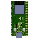
This project is a reference project for ESP32-S3-MINI-1 to develop your IoT ideas. The board has RGB LEDs, USB C for firmware, EN and BOOT buttons, and 2 IO connectors for development
#IoT #WiFi #MCU #RF #ESP32 #project #referenceDesign #simple-embedded #espressif #template #reference-design
Properties
Pricing & Availability
Distributor | Qty 1 |
|---|---|
Digi-Key | $4.26–$5.89 |
LCSC | $5.34 |
Mouser | $2.78 |
Controls
Welcome 👋
Flux helps you build PCBs faster with an AI teammate!
Create your account to collaborate, stay updated, fork your own version, and get instant answers from our AI agent.
arjunpc08
copilot
-
ESP32-S3-MINI-1 (U1): The core microcontroller unit (MCU) designed for Internet of Things (IoT) applications, featuring Wi-Fi and Bluetooth connectivity. It has numerous GPIO pins for interfacing with other components.
-
RGB LED (LED1): An RGB LED for visual feedback, allowing different colors to be displayed by mixing red, green, and blue.
-
USB-C Connector (J1): Provides power to the board and a connection interface for programming the firmware onto the ESP32-S3-MINI-1.
-
Buttons (SW1, SW2): Typically used as reset (EN) and boot (BOOT) buttons. These are essential for programming the device and resetting it.
-
IO Connectors (J2, J3): These connectors provide access to the GPIO pins of the ESP32-S3-MINI-1, allowing various peripherals to be connected for development purposes.
-
Resistors (R1, R2, ...): These resistors are used for purposes such as setting up pull-up/pull-down for IOs, ensuring proper LED current, and interfacing with other components.
-
Capacitors (C1, C2, ...): Capacitors are used for decoupling and noise reduction on power lines, and sometimes for timing or filtering purposes.
-
Diode (D1): Likely used for protecting the circuit from incorrect power supply polarity.
-
Inductor (L1): Used in conjunction with IC1 (a power management IC) for creating a stable power supply for the device.
-
TPS62130RGTR (IC1): A power management integrated circuit (PMIC) from Texas Instruments, intended to provide a stable power supply to the MCU and other components.
Features:-
IoT Capability: With built-in Wi-Fi and Bluetooth, the ESP32-S3-MINI-1 is ideal for IoT applications requiring remote connectivity.
-
Development-Friendly: The inclusion of USB-C for firmware updates, buttons for EN and BOOT, and IO connectors make this board suitable for development and testing of various applications.
-
Visual Feedback: The RGB LED offers a simple, visual means of feedback for software states or diagnostics.
-
Flexible Power Options: The design incorporates a power management IC (TPS62130RGTR) and various power nets (+5V, 3V3), suggesting flexibility in power sources and management for stable operation.
Licensing: