Interface ICs
An interface IC is a type of integrated circuit that is designed to facilitate communication between two devices or systems. These devices are commonly used in electronic systems to enable the transfer of data and control signals between different components or subsystems. Some common use cases for interface ICs include connecting microcontrollers to peripherals such as sensors or displays, linking multiple processors together in a network, and enabling communication between devices using different communication protocols. Flux.ai has the world's largest community-driven public library of interface ICs, with footprints, symbols, datasheets, and simulation models. This library is a valuable resource for engineers and designers who need access to accurate and up-to-date information on these important components. Whether you are working on a new design project or simply looking to learn more about interface ICs, Flux.ai is an excellent resource to help you find the information you need.
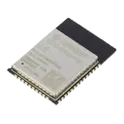
ESP32-WROOM-32E (16MB)
The ESP32-WROOM-32E (16MB) is a highly integrated Wi-Fi + Bluetooth + Bluetooth Low Energy (BLE) module developed by Espressif. It is based on the ESP32-D0WD-V3 chip and features a dual-core processor, rich peripherals, and large flash memory—making it ideal for IoT, embedded systems, and wireless applications. This module is part of the upgraded WROOM-32E series, offering improved RF performance, better stability, and enhanced reliability compared to earlier versions like the 32D. Key Features (16MB Variant) Processor & Memory Dual-core Xtensa® 32-bit LX6 CPU, up to 240 MHz 520 KB SRAM + 448 KB ROM 16 MB SPI Flash (large storage for firmware/data) Optional variants with PSRAM for memory-intensive tasks Connectivity 2.4 GHz Wi-Fi (802.11 b/g/n) Bluetooth v4.2 (BR/EDR + BLE) Integrated PCB antenna (no external antenna needed) Peripherals & Interfaces Up to 26–38 GPIOs (depending on usage) Supports: UART, SPI, I2C, I2S PWM (LED & motor control) ADC, DAC Capacitive touch sensors SD/SDIO/MMC, CAN (TWAI) Electrical & Physical Operating voltage: 3.0V – 3.6V Operating temperature: –40°C to +85°C (industrial range) Compact size: 18 × 25.5 × 3.1 mm Typical Applications Smart home devices (lighting, appliances) IoT sensors and gateways Industrial automation systems Wearables and smart gadgets Audio/voice processing (thanks to dual-core + large flash) #module #ESP32 #16MB
69 Uses0 StarsTPD4E05U06DQAR
14VC Clamp 2.5A@8/20us Ipp TVS DIODE USON-10(1x2.5) The TPDxE05U06 is a family of unidirectional Transient Voltage Suppressor (TVS) based Electrostatic Discharge (ESD) protection diodes with ultra-low capacitance. Each device can dissipate ESD strikes above the maximum level specified by the IEC 61000-4-2 international standard. The TPDxE05U06s ultra-low loading capacitance makes it ideal for protecting any high-speed signal pins. Typical applications for TPDxE05U06 includes high speed signal lines in HDMI 1.4b, HDMI 2.0, USB 3.0, MHL, LVDS, DisplayPort, PCI-Express® , eSata, and V-by-One® HS. Features • IEC 61000-4-2 Level 4 ESD Protection – ±12-kV Contact Discharge – ±15-kV Air Gap Discharge • IEC 61000-4-4 EFT Protection – 80 A (5/50 ns) • IEC 61000-4-5 Surge Protection – 2.5 A (8/20 µs) • IO Capacitance 0.42 pF to 0.5 pF (Typical) • DC Breakdown Voltage 6.5 V (Minimum) • Ultra low Leakage Current 10 nA (Maximum) • Low ESD Clamping Voltage • Industrial Temperature Range: –40°C to +125°C • Easy Straight-Through Routing Packages Application • HDMI 1.4b • HDMI 2.0 • USB 3.0 • MHL • LVDS Interfaces • DisplayPort • PCI-Express® • eSata Interfaces • V-by-One® HS #Commonpartlibrary #TVS diode #Circuit Protection
233 Uses0 StarsTPS259530DSGR
Electronic Fuse Regulator 4A 8-WSON (2x2) The TPS259530DSGR is a compact, integrated eFuse protection device designed to provide robust power-path management for low-voltage DC systems, particularly nominal five-volt rails. It combines multiple protection and control features into a single solution, enabling safe distribution of power to downstream circuitry while minimizing the need for external components. The device supports controlled inrush current during startup, continuous current monitoring, and rapid fault response to protect both the power source and the load. Integrated protection mechanisms include overvoltage protection, undervoltage lockout, overcurrent limiting, thermal shutdown, and reverse current blocking. This makes the device well suited for applications requiring high reliability, such as embedded systems, industrial electronics, consumer devices, and communication equipment. Functional Description The device operates as a high-side protection switch using an internal MOSFET to control current flow from the input supply to the load. It monitors input voltage, output current, and internal temperature to ensure operation within safe limits. When a fault condition such as overcurrent or overvoltage is detected, the device limits or interrupts current flow to prevent damage. The integrated control loop provides smooth startup by limiting inrush current and preventing supply droop. Reverse current blocking prevents unwanted current flow from the output back to the input when the input supply is removed or drops below the output level. Electrical Characteristics The device supports operation across a wide input voltage range suitable for low-voltage DC systems, including typical five-volt rails. It features an adjustable overvoltage protection threshold aligned with five-volt system requirements, along with configurable undervoltage lockout to ensure proper system startup and shutdown behavior. The current limit is externally programmable, allowing flexibility for different load conditions. The device exhibits low on-resistance to minimize power dissipation and voltage drop during normal operation. Protection Features The TPS259530DSGR integrates multiple protection functions to enhance system robustness. Overvoltage protection prevents excessive input voltage from reaching the load. Undervoltage lockout ensures the device only operates when the input supply is within a valid range. Overcurrent protection actively limits current during fault conditions and can respond rapidly to short circuits. Thermal shutdown protects the device from overheating by disabling operation when internal temperature exceeds safe limits. Reverse current blocking prevents backflow of current, safeguarding both the source and load. Control and Interface The device includes an enable control input that allows external control of the power path. It supports configurable behavior for fault response and recovery, depending on system design. External components can be used to set thresholds such as current limit and undervoltage lockout, providing design flexibility. Status signaling allows system-level monitoring of fault conditions. Mechanical and Package Information The TPS259530DSGR is provided in a compact surface-mount package suitable for space-constrained applications. The package is optimized for thermal performance and efficient PCB layout, enabling reliable operation under varying load conditions. It is supplied in tape-and-reel format for automated assembly processes. Applications This device is intended for use in systems requiring reliable power distribution and protection. Typical applications include five-volt power rails in embedded systems, industrial control modules, consumer electronics, communication devices, and peripheral power management circuits. Summary The TPS259530DSGR offers an integrated, high-reliability solution for power path protection and management in low-voltage systems. Its combination of protection features, configurability, and compact form factor makes it a widely used choice for safeguarding five-volt supply rails in modern electronic designs. #commonpartslibrary #integratedcircuit #powermanagement
1.0k Uses0 StarsIHDM1008BCEV4R7M30
4.7 µH Unshielded Drum Core, Wirewound Inductor 62 A 0.95mOhm Max Vertical, 2 PC Pin The IHDM1008BCEV4R7M30 is a surface-mount power inductor designed for energy storage and filtering in switching power supplies and DC-DC converter circuits. It provides stable inductance characteristics under varying current conditions, making it suitable for applications requiring efficient power conversion and noise suppression. The device is constructed using a magnetically shielded structure to minimize electromagnetic interference and ensure reliable operation in densely populated circuit environments. Its design supports high current handling capability while maintaining low core losses, contributing to overall system efficiency. Functional Overview The inductor stores energy in its magnetic field when current flows through it and releases that energy when the current changes. This behavior is essential for smoothing current in switching regulators and maintaining stable voltage levels in power circuits. Its low resistance winding helps reduce power loss, while the magnetic shielding limits flux leakage, improving performance in sensitive electronic systems. The component is optimized for high-frequency operation typically found in modern power management designs. Electrical Characteristics The device provides a fixed inductance value with stable performance across a range of operating currents. It supports relatively high saturation current levels, allowing it to function effectively in power circuits without significant degradation of inductance. Low direct current resistance contributes to improved efficiency and reduced heat generation. The inductor is designed to maintain consistent electrical behavior across typical operating temperatures and frequencies used in switching applications. Interface Requirements The component features standard surface-mount terminals for direct placement onto printed circuit boards. Proper soldering and pad design are required to ensure mechanical stability and optimal electrical performance. Placement considerations should include minimizing loop area and proximity to switching elements to reduce noise and maximize efficiency. Operating Conditions The inductor is intended for operation across a wide temperature range suitable for consumer and industrial electronics. It is capable of maintaining performance under continuous load conditions and varying thermal environments. Adequate thermal management and airflow may be necessary in high-current applications to prevent excessive temperature rise. Protection and Reliability Features The device is constructed with durable materials to ensure long-term reliability under electrical and thermal stress. Its magnetically shielded design reduces susceptibility to external interference and limits emissions that could affect nearby components. It is designed to withstand standard handling and soldering processes associated with surface-mount assembly. Packaging and Integration The IHDM1008BCEV4R7M30 is provided in a compact surface-mount package optimized for automated assembly processes. Its form factor allows efficient use of board space while supporting high-performance power designs. The package design ensures secure mounting and consistent electrical contact in high-density circuit layouts. Applications Typical applications include DC-DC converters, voltage regulator modules, power management circuits, filtering stages, and energy storage elements in portable devices, industrial equipment, and communication systems. #commonpartslibrary #inductors
0 Uses0 StarsSN65HVD230DR
1/1 Transceiver Half CANbus 8-SOIC The SN65HVD230DR is a high-speed Controller Area Network (CAN) transceiver designed to interface a CAN protocol controller with the physical two-wire CAN bus. It operates as a differential line driver and receiver, translating logic-level signals into robust bus-level signals suitable for automotive, industrial, and distributed control applications. The device is optimized for reliable communication in electrically noisy environments and supports low-power operation, making it suitable for systems requiring energy efficiency and extended operational stability. This transceiver conforms to widely adopted CAN physical layer standards and is intended for use in systems requiring high data integrity, fault tolerance, and electromagnetic compatibility. It integrates protection features and supports standby functionality to reduce system power consumption when communication is inactive. Functional Overview The device provides bidirectional signal conversion between a CAN controller and the differential CAN bus lines. It features a transmit data input and a receive data output, enabling full-duplex communication at the protocol level. The driver stage generates differential output signals on the bus, while the receiver stage detects and translates bus signals back into logic-level data. An internal control mechanism allows the device to enter a low-power standby mode, reducing current consumption when active communication is not required. The transceiver includes slope control capability to manage signal edge rates, which helps minimize electromagnetic interference and improves signal integrity across the network. Electrical Characteristics The transceiver operates from a single low-voltage supply and is designed for compatibility with modern microcontrollers and digital logic systems. It provides differential output drive capability with controlled rise and fall characteristics. The receiver is designed with high input sensitivity and noise immunity to ensure accurate signal detection under varying bus conditions. The device includes thermal protection and safeguards against bus faults, including short-circuit conditions. Its internal circuitry is designed to maintain stable operation across a wide range of environmental conditions and supply variations. Interface Requirements The logic interface is compatible with standard digital input and output levels, allowing direct connection to a CAN controller. The bus interface consists of two differential lines that connect to the CAN network. Proper termination and layout practices are required to ensure optimal communication performance and compliance with CAN network design guidelines. Operating Conditions The device is intended for operation across a broad temperature range suitable for industrial and automotive environments. It maintains functional integrity under typical voltage fluctuations and environmental stresses encountered in embedded systems. Protection and Reliability Features The transceiver incorporates protection mechanisms to guard against overcurrent, thermal overload, and electrostatic discharge. It is designed to maintain communication reliability even in the presence of transient disturbances and electrical noise. Packaging and Integration The SN65HVD230DR is provided in a compact surface-mount package suitable for automated assembly. Its pin configuration supports straightforward integration into printed circuit board designs with minimal external components. #CommonPartsLibrary #IntegratedCircuits #Interface #Drivers #Receivers #Transceivers #65HVD230
98 Uses0 StarsSSW-122-02-G-S
22 Position Receptacle Connector 0.100" (2.54mm) Through Hole Gold The SSW-122-02-G-S is a surface-mount, single-row socket strip designed for reliable board-to-board or component interconnection in electronic assemblies. It is part of a standardized connector series intended for applications requiring compact form factor, consistent electrical performance, and ease of automated placement. The component features a low-profile design suitable for dense PCB layouts and is commonly used in prototyping, embedded systems, and production-level electronics. Design and Construction The connector is manufactured with precision-aligned contacts housed in a high-temperature thermoplastic body, enabling compatibility with standard reflow soldering processes. The contact system is engineered to ensure stable mechanical retention and consistent electrical conductivity, supporting repeated mating cycles without significant degradation. The materials used provide durability, resistance to thermal stress, and compliance with common industry standards for electronic components. Electrical Characteristics The device is intended to provide reliable signal transmission with minimal contact resistance. It supports low to moderate current applications typical of signal-level interconnections. The contact plating is designed to reduce oxidation and maintain stable electrical performance over time. Mechanical Features The connector is configured as a single-row socket with a defined pitch spacing suitable for standard header interfaces. Its surface-mount termination allows for secure attachment to printed circuit boards while minimizing required board space. The structure supports proper alignment during assembly and ensures consistent engagement with corresponding mating connectors. Applications This component is widely used in applications such as microcontroller boards, communication modules, sensor interfaces, and general-purpose electronic systems. It is suitable for both development environments and final product integration where dependable and space-efficient connectivity is required. Compliance and Reliability The SSW-122-02-G-S is designed to meet common industry requirements for environmental and mechanical reliability. It is typically compliant with RoHS standards and suitable for use in a variety of operating conditions encountered in commercial and industrial electronics. #commonpartslibrary #connector #header
18 Uses0 StarsENW-89854A3KF
802.15.4, Bluetooth Bluetooth v5.0 Transceiver Module Integrated, Ceramic Patch Surface Mount General Description ENW-89854A3KF refers to a designated component, system, or configuration intended for engineering deployment within a defined operational environment. It is designed to meet performance, reliability, and integration requirements consistent with modern engineering standards. The specification outlines the functional expectations, structural considerations, and operational behavior necessary to ensure compatibility with associated systems and to support stable, efficient performance under expected conditions. Scope This specification defines the requirements and characteristics of ENW-89854A3KF, including its intended functionality, performance expectations, environmental tolerance, and integration considerations. It applies to design, development, testing, and implementation phases. Functional Requirements The system shall perform its intended function consistently within defined operational parameters. It shall support continuous operation where required and maintain stability under varying load conditions. The design shall ensure predictable behavior and allow for monitoring and control as necessary. Performance Characteristics The component shall operate efficiently within acceptable performance thresholds. It shall maintain responsiveness and reliability during standard and peak conditions. Performance degradation, if any, shall remain within acceptable engineering tolerances. Design Considerations The design shall prioritize durability, maintainability, and scalability. Materials and architecture shall be selected to ensure long-term operation with minimal failure risk. The system shall support ease of integration with existing infrastructure and allow for future modifications if required. Environmental Conditions The system shall operate within specified environmental ranges, including temperature, humidity, and exposure conditions relevant to its deployment context. Protective measures shall be incorporated where necessary to prevent damage or performance loss. Interface and Integration ENW-89854A3KF shall be compatible with associated systems and interfaces. Communication protocols, physical connections, and data exchange mechanisms shall align with standard engineering practices to ensure seamless integration. Safety and Compliance The design and operation shall adhere to applicable safety standards and regulatory requirements. The system shall include safeguards to prevent hazardous conditions and ensure safe handling and operation. Testing and Validation The system shall undergo verification and validation to confirm compliance with this specification. Testing shall include functional validation, performance assessment, and environmental resilience checks. Maintenance and Support The system shall be designed for ease of maintenance, including accessibility for inspection, repair, or replacement. Documentation and support provisions shall be available to ensure proper lifecycle management. #commonpartslibrary #integratedcircuit #transceiver #wireless #rf
0 Uses0 Stars0603L050YR
Polymeric PTC Resettable Fuse 6V 500 mA Ih Surface Mount 0603 (1608 Metric), Concave polyfuse 500mA 0603 The 0603L050YR is a surface-mount resettable fuse based on polymeric positive temperature coefficient technology, designed to provide overcurrent protection in compact electronic circuits. Under normal operating conditions, the device exhibits low resistance and allows current to pass with minimal power loss. When exposed to an overcurrent condition, the device transitions to a high-resistance state, effectively limiting the current and protecting downstream components. Once the fault condition is removed and power is cycled or the device cools, the fuse automatically resets to its original low-resistance state. This component is optimized for space-constrained applications requiring reliable, resettable protection, such as portable electronics, battery-powered systems, and low-voltage signal lines. Its small form factor enables integration into dense PCB layouts while maintaining compliance with industry safety standards for overcurrent protection. Package and Mounting: Surface-mount device in standard 0603 footprint, compatible with automated assembly processes including reflow soldering. Electrical Characteristics: The device is designed to maintain normal operation at a defined hold current level and transition to a protective state when the current exceeds its trip threshold. It operates within low-voltage circuits and provides fast response to fault conditions while minimizing nuisance tripping under typical load variations. Functional Behavior: The fuse operates by increasing resistance sharply in response to thermal energy generated by excess current. This behavior reduces current flow and limits fault energy. After removal of the overcurrent condition, the device gradually returns to its conductive state, enabling repeated use without replacement. Applications: Suitable for use in power lines, battery packs, USB interfaces, consumer electronics, and other low-voltage systems where resettable overcurrent protection is required. Compliance and Reliability: Designed to meet relevant safety and environmental standards for electronic components, ensuring stable performance across specified operating conditions and long-term reliability in field applications. #commonpartslibrary #fuse #Circuit-Protection #PTC #ptc #polymeric
201 Uses0 StarsTPD1E05U06DPYR
14V Clamp 2.5A (8/20µs) Ipp Tvs Diode Surface Mount 2-X1SON (1x.60) TVS diode USB VBUS 5V TVS diode USB VBUS 5V ESD protection General Description The TPD1E05U06DPYR is a single-channel transient voltage suppression device designed to protect sensitive electronic components from electrostatic discharge (ESD) and other transient voltage events. It is engineered for high-speed signal applications, offering low capacitance to preserve signal integrity while providing robust protection. The device is suitable for integration into compact and portable electronic systems where space, reliability, and performance are critical. Device Identification Part number: TPD1E05U06DPYR Device classification: ESD protection diode / transient voltage suppressor Manufacturer: Commonly associated with Texas Instruments Mounting type: Surface-mount Package style: Ultra-small leadless package (e.g., X2SON/DFN) Functional Description Protects circuits from high-voltage transients caused by ESD events Limits voltage spikes by clamping them to safe levels Maintains signal quality by minimizing added capacitance Operates transparently under normal signal conditions Provides fast response to transient disturbances Performance Characteristics Low capacitance suitable for high-speed data lines High ESD protection capability compliant with standard test models Low leakage current during normal operation Fast transient response time Stable performance across specified operating conditions Electrical Characteristics Designed for low-voltage applications (approximately 5 V working range) Low clamping voltage to protect downstream components Minimal dynamic resistance Very low input/output capacitance High reliability under repeated ESD stress Application Scope High-speed communication interfaces such as USB, HDMI, and display ports Mobile phones, tablets, and wearable electronics Embedded systems and microcontroller interfaces Consumer and industrial electronic equipment Data and signal line protection in compact devices Mechanical and Physical Properties Compact footprint for high-density PCB layouts Leadless package for improved mechanical robustness Compatible with standard surface-mount assembly processes Designed for automated manufacturing environments Integration Guidelines Install as close as possible to the external connector or entry point Ensure a low-impedance path to ground for optimal protection Minimize trace length between the device and the protected line Consider layout practices to preserve high-speed signal integrity Verify compatibility with system voltage and interface requirements #commonpartslibrary #circuitprotection #tvsdiode
676 Uses0 Stars