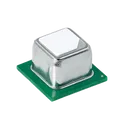
SCD41-D-R1
Air Quality Sensor CO2 Sensor 2.5V/3.3V/5V 20-Pin SMD EP T/R The SCD41-D-R1 is a miniature photoacoustic carbon dioxide sensor module developed by Sensirion for high-accuracy environmental sensing applications. The device integrates a CO₂ sensing element, temperature sensor, humidity sensor, optical components, calibration memory, and digital signal processing into a compact surface-mount package suitable for embedded systems and portable electronics. The sensor utilizes photoacoustic sensing technology to provide precise carbon dioxide concentration measurements while maintaining low power consumption and long-term stability. Integrated humidity and temperature sensing capabilities enable environmental compensation and simplify system integration by reducing the need for external sensors. The SCD41 communicates through a standard I²C digital interface and supports automatic self-calibration functions for reliable long-term operation. Its compact footprint and low energy requirements make it suitable for battery-powered devices, smart building systems, HVAC equipment, indoor air quality monitoring systems, and IoT applications. The module is factory calibrated and designed for continuous monitoring of indoor air quality conditions. The integrated architecture minimizes external component requirements while enabling accurate sensing performance across a wide operating range. Key Features Photoacoustic CO₂ sensing technology Integrated temperature and humidity sensing High accuracy carbon dioxide measurement I²C digital communication interface Low power consumption operation Automatic self-calibration support Compact surface-mount package Factory calibrated output Long-term measurement stability Optimized for indoor air quality applications Low-profile PCB mounting design RoHS and halogen-free compliant Electrical Characteristics Low-voltage supply operation Low average current consumption suitable for portable devices Integrated digital signal processing Non-volatile calibration memory Standard I²C communication compatibility Stable operation across industrial environmental conditions Mechanical Characteristics Compact SMD package for space-constrained applications Surface-mount assembly compatible Low-profile package structure Integrated optical cavity and sensing chamber Moisture-sensitive device requiring controlled handling during assembly Functional Characteristics Real-time carbon dioxide concentration monitoring Simultaneous temperature and humidity measurement Automatic environmental compensation Continuous and periodic measurement modes Fast startup and measurement response Long operational lifetime with stable calibration Optimized airflow design for accurate sensing Suitable for continuous indoor environmental monitoring Typical Applications Indoor air quality monitoring systems Smart thermostats and HVAC controllers Building automation equipment Demand-controlled ventilation systems Portable environmental monitoring devices Smart home and IoT products Air purification systems Occupancy and ventilation monitoring Battery-powered sensing devices Consumer and industrial environmental monitoring equipment #commonpartslibrary #sensor #airquality... show more458 Uses
0 Stars
PPTC191LFBN-RC
19 Position Header Connector 0.100" (2.54mm) Through Hole Tin 1x19 pin header 2.54mm This component is a single-row female header connector designed for general-purpose board-to-board and wire-to-board interconnections. It provides a reliable and cost-effective solution for standard pitch connectivity in electronic assemblies. The connector is commonly used in prototyping, development boards, and production systems where modular connections and ease of assembly are required. Its design supports compatibility with standard male pin headers, making it suitable for a wide range of applications in industrial, consumer, and embedded electronics. Key Features The connector features a single-row configuration with standard pitch spacing, enabling compatibility with widely used pin header systems. It is constructed with durable insulating material and conductive contacts that provide stable electrical performance. The contacts are designed to ensure consistent mating force and reliable signal transmission. The component supports through-hole mounting for strong mechanical retention and ease of soldering. Its construction allows repeated mating cycles while maintaining contact integrity. Electrical Characteristics The connector is designed to support typical signal and low-power applications in electronic circuits. It provides consistent electrical contact with low contact resistance and stable conductivity under normal operating conditions. The materials and plating are selected to ensure reliable performance over time, minimizing oxidation and degradation during use. Mechanical and Material Characteristics The housing is made from a high-temperature thermoplastic material suitable for standard soldering processes. The contacts are formed from conductive metal alloy and finished with a protective plating to enhance durability and conductivity. The connector is designed for vertical mounting orientation and aligns with standard printed circuit board layouts for through-hole components. Thermal Characteristics The component is suitable for typical operating temperature ranges encountered in electronic assemblies. The housing material is resistant to heat generated during soldering and normal operation, ensuring structural integrity and long-term reliability. Applications This connector is widely used in embedded systems, development platforms, consumer electronics, industrial control systems, and communication equipment. It is ideal for applications requiring modular connectivity, easy replacement, and reliable electrical interfacing between boards or components. Compliance and Standards The component is manufactured in accordance with industry standards for electronic connectors and is suitable for use in systems requiring dependable mechanical and electrical performance. It supports common environmental and material compliance requirements for modern electronic manufacturing. #commonpartslibrary #connector #header... show more95 Uses
0 Stars
LM65645SRZTRQ1
Buck Switching Regulator IC Positive Adjustable (Fixed) 0.8V (3.3V, 5V) 1 Output 4.5A 20-WFQFN Exposed Pad The LM656x5-Q1 are a family of automotive buck converters designed for high efficiency, high-power density, and ultra-low electromagnetic interference (EMI). The converters operate over a wide input voltage range of 3V to 65V (70V transient < 100ms), reducing the need for external input surge protection. The LM656x5-Q1 comes with pin selectable fixed output voltages of 3.3V and 5V or in adjustable configuration. The low EMI operation is enabled with minimized loop inductance and optimized switch node slew rate. A pin-selectable ±5% or ±10% dual-random spread spectrum (DRSS) significantly reduces peak emissions through a combination of triangular and pseudo-random modulation while keeping output voltage ripple very low. The current-mode control architecture with a 30ns typical minimum on-time allows high conversion ratios at high frequencies coupled with a fast transient response and excellent load and line regulation. Features • AEC-Q100 qualified for automotive applications: – Temperature grade 1: –40°C to +125°C, TA • Wide input voltage range: 3V to 65V (70V transient < 100ms) – Meets LV148 / ISO21780 requirements • Designed for low EMI requirements – Facilitates CISPR 25 class 5 compliance – Mode pin configurable ±5% or ±10% dualrandom spread spectrum reducing peak emissions – Enhanced HotRod™ QFN package with symmetrical pinout – Switching frequency from 300kHz to 2.2MHz – Pin-configurable AUTO or FPWM operation – Internal compensation, current limit, and TSD • Low minimum on time: 40ns (maximum) – Enables 36VIN to 3.3VOUT conversion at 2.2MHz • High-efficiency power conversion at all loads – > 94% peak efficiency at 24VIN, 5VOUT, 400kHz – 2.5µA switching input current at no load • High power density – 3.6mm × 2.6mm, wettable flank, 20-pin package – Pin compatible with 36V LM654x0-Q1 – ϴJA = 24.0°C/W (LM65645-Q1EVM) • Create a custom design using the LM656x5-Q1 with the WEBENCH® Power Designer 2 Applications • Advanced driver assistance systems (ADAS) • Automotive infotainment and cluster • Hybrid, electric, and powertrain systems #AutomotiveElectronics #BuckConverter #DCDCConverter #PowerManagement #VoltageRegulator #SynchronousBuck #LowEMI #AECQ100 #TexasInstruments #EmbeddedSystems... show more94 Uses
0 Stars
BSC030N10NS5SCATMA1
N-Channel 100 V 171A (Tc) 188W (Tc) Surface Mount PG-WSON-8-2 The BSC030N10NS5SCATMA1 specification defines the engineering requirements for an N-channel power MOSFET designed for high-efficiency switching and power management applications. This specification establishes the functional, electrical, mechanical, thermal, environmental, and quality requirements necessary to ensure reliable switching performance, low conduction losses, and long-term operational stability in power electronic systems. The device is intended for use in DC-DC converters, synchronous rectification circuits, motor control systems, battery management systems, power distribution modules, and industrial electronic equipment. It provides low on-state resistance, fast switching characteristics, and efficient power handling, making it suitable for high-frequency and high-current applications requiring optimized efficiency and thermal performance. Engineering Requirements The power MOSFET shall be manufactured using advanced semiconductor fabrication processes and qualified materials to ensure consistent electrical characteristics, high switching efficiency, and reliable long-term operation. The device shall maintain stable performance under specified voltage, current, and environmental operating conditions. Electrical characteristics shall provide low on-state resistance, high current-carrying capability, low gate charge, and fast switching performance to minimize conduction and switching losses. The device shall maintain stable operation during repetitive switching cycles, transient load conditions, and dynamic power management applications. Thermal performance shall support efficient heat dissipation through the package structure and printed circuit board interface. The component shall maintain electrical integrity and operational reliability within the specified junction temperature range during continuous and intermittent high-power operation. Mechanical construction shall be suitable for automated surface-mount assembly and compatible with standard solder reflow manufacturing processes. The package shall withstand vibration, thermal cycling, mechanical handling, and environmental exposure without degradation of electrical or mechanical performance. Workmanship shall be free from defects including contamination, cracks, bond failures, package deformation, or structural inconsistencies. Inspection, validation, and testing shall be conducted using calibrated equipment and controlled quality procedures to verify compliance with all applicable engineering and manufacturing requirements. Any deviation from this specification shall require formal engineering evaluation, documented technical justification, and approval through the established engineering change control process. Documentation Supporting documentation shall include engineering drawings, electrical performance specifications, thermal characterization reports, qualification records, inspection reports, material declarations, reliability data, and revision-controlled manufacturing documentation. All documentation shall be maintained under formal configuration management and quality assurance systems to ensure complete product traceability. Revision Control Any modification to this specification shall be managed through the formal engineering change management process. All revisions shall undergo technical review, validation, and approval before implementation to ensure continued compliance with design intent and applicable engineering standards. #EngineeringSpecification #PowerMOSFET #NChannelMOSFET #PowerElectronics #PowerManagement #MotorControl #DCDCConverter #Semiconductor #QualityAssurance #EngineeringDocumentation #commonpartslibrary #transistor #mosfet... show more0 Uses
0 Stars
Si8271GBD-IS
4A Gate Driver RF Coupling 2500Vrms 1 Channel 8-SOIC Confirmed — this is a Skyworks (formerly Silicon Labs) Si827x-family isolated gate driver, single-channel, with deglitch and UVLO, in the "GBD" variant (3V UVLO threshold). Here's the spec. Engineering Specification — Si8271GBD-IS Manufacturer: Skyworks Solutions, Inc. (formerly Silicon Labs) Device Family: Si827x ISOdriver General Description The Si8271GBD-IS is a single-channel isolated gate driver integrated circuit manufactured by Skyworks Solutions, designed to drive power switching devices such as MOSFETs, IGBTs, and wide-bandgap SiC or GaN FETs in power conversion applications. The device uses Skyworks' proprietary silicon-based galvanic isolation technology rather than the optical isolation used in traditional optocoupler-based gate drivers, providing a more robust, longer-lasting, and more precisely matched isolation barrier between the low-voltage control circuitry and the high-voltage power switching stage. This isolation approach delivers several advantages over legacy optocoupler solutions, including significantly higher common-mode transient immunity, which allows the device to maintain reliable signal integrity even when subjected to the very fast voltage transients generated by high-speed switching in modern power converters. The device's high noise immunity prevents these switching-induced transients from corrupting the gate drive signal, eliminating a common failure mode in less robust isolated driver designs where fast edge rates can cause spurious switching or loss of control. The silicon isolation technology also provides tighter timing specifications, reduced timing variation across temperature and device lifetime, and better part-to-part matching than optocoupler-based alternatives, all of which contribute to more predictable and efficient power stage operation. The device includes an integrated de-glitch filtering circuit on its input, which screens out short noise spikes or unwanted transitions on the control input before they can be passed through to the gate drive output, improving overall system robustness in electrically noisy environments. Undervoltage lockout protection is built into the device, automatically disabling the gate drive output if the supply voltage falls below a safe operating threshold, protecting the driven power switch from being driven with insufficient gate voltage, which could otherwise lead to excessive conduction losses or device damage. The device also provides a dead-time programming feature, allowing designers to precisely tune the timing margin between switching transitions in half-bridge or similar topologies, helping to prevent shoot-through conditions while minimizing unnecessary dead time that would otherwise reduce converter efficiency. The Si8271GBD-IS operates from a wide input supply voltage range and supports drive voltages suitable for a broad range of gate drive requirements, making it adaptable to many different power switch types and converter topologies. It is built to operate reliably across a wide ambient temperature range, supporting use in demanding industrial, telecom, and renewable energy power conversion environments. The device is housed in a compact surface-mount package suited to dense power converter board layouts, and its construction reflects the long-life, high-reliability design philosophy that distinguishes silicon-isolation-based gate drivers from optocoupler-based alternatives. Spec Sheet Identification Part Number: Si8271GBD-IS Device Family: Si827x ISOdriver series Manufacturer: Skyworks Solutions (formerly Silicon Labs) Functional Classification Device Type: Single-channel isolated gate driver Isolation Technology: Proprietary silicon-based galvanic isolation Driven Device Types: MOSFETs, IGBTs, SiC FETs, GaN FETs Output Configuration: Separate pull-up/pull-down driver outputs Isolation & Noise Performance Isolation Withstand Voltage: High-voltage reinforced isolation rating per UL1577 and VDE0884 standards Common-Mode Transient Immunity (CMTI): High-performance CMTI rating for fast-switching robustness Input Filtering: Integrated de-glitch circuit for noise rejection Protection & Control Features Undervoltage Lockout (UVLO): Integrated UVLO fault protection with driver shutdown Dead-Time Control: Precision dead-time programmability via dedicated control pin Input Logic: TTL-level compatible input with wide noise-margin hysteresis Electrical Characteristics Input Supply Voltage Range: Wide-range low-voltage logic supply Drive Supply Voltage: Higher-voltage gate drive supply rail support Propagation Delay: Fast, tightly specified propagation timing Environmental & Qualification Operating Temperature Range: Extended industrial temperature range RoHS Compliance: Yes Lifecycle Status: Active production Package Package Type: Narrow-body small-outline surface-mount package (SOIC-8) Mounting: Surface mount technology (SMT) Packaging Format Supply Format: Tube or tape-and-reel packaging options #Si8271 #Si827x #Skyworks #SiliconLabs #IsolatedGateDriver #ISOdriver #GateDriverIC #MOSFETDriver #IGBTDriver #SiCFET #GaNDriver #PowerElectronics #GalvanicIsolation #CMTI #SOIC #SurfaceMount #SemiconductorIC #EngineeringSpec #ComponentLibrary #CommonPartsLibrary #RoHSCompliant... show more0 Uses
0 Stars

MP28167-A
The MP28167-A is a synchronous, four-switch, integrated buck-boost converter capable of regulating output voltage across a wide 2.8V to 22V input voltage range with high efficiency. The integrated output voltage scaling and adjustable output current limit functions meet USB power delivery (PD) requirements. The MP28167-A uses constant-on-time (COT) control in buck mode and constant-off-time control in boost mode, providing fast load transient response and smooth buck-boost mode transient. The MP28167-A provides automatic pulse-frequency modulation (PFM) mode, automatic pulse-width modulation (PWM) mode, and forced PWM switching mode. It also provides a configurable output constant current (CC) limit that supports flexible design for different applications. Full protection features include over-current protection (OCP), over-voltage protection (OVP), under-voltage protection (UVP), configurable soft start (SS), and thermal shutdown. The MP28167-A is available in a QFN-16 (3mmx3mm) package.... show more16 Uses
0 Stars
TPS259530DSGR
Electronic Fuse Regulator 4A 8-WSON (2x2) The TPS259530DSGR is a compact, integrated eFuse protection device designed to provide robust power-path management for low-voltage DC systems, particularly nominal five-volt rails. It combines multiple protection and control features into a single solution, enabling safe distribution of power to downstream circuitry while minimizing the need for external components. The device supports controlled inrush current during startup, continuous current monitoring, and rapid fault response to protect both the power source and the load. Integrated protection mechanisms include overvoltage protection, undervoltage lockout, overcurrent limiting, thermal shutdown, and reverse current blocking. This makes the device well suited for applications requiring high reliability, such as embedded systems, industrial electronics, consumer devices, and communication equipment. Functional Description The device operates as a high-side protection switch using an internal MOSFET to control current flow from the input supply to the load. It monitors input voltage, output current, and internal temperature to ensure operation within safe limits. When a fault condition such as overcurrent or overvoltage is detected, the device limits or interrupts current flow to prevent damage. The integrated control loop provides smooth startup by limiting inrush current and preventing supply droop. Reverse current blocking prevents unwanted current flow from the output back to the input when the input supply is removed or drops below the output level. Electrical Characteristics The device supports operation across a wide input voltage range suitable for low-voltage DC systems, including typical five-volt rails. It features an adjustable overvoltage protection threshold aligned with five-volt system requirements, along with configurable undervoltage lockout to ensure proper system startup and shutdown behavior. The current limit is externally programmable, allowing flexibility for different load conditions. The device exhibits low on-resistance to minimize power dissipation and voltage drop during normal operation. Protection Features The TPS259530DSGR integrates multiple protection functions to enhance system robustness. Overvoltage protection prevents excessive input voltage from reaching the load. Undervoltage lockout ensures the device only operates when the input supply is within a valid range. Overcurrent protection actively limits current during fault conditions and can respond rapidly to short circuits. Thermal shutdown protects the device from overheating by disabling operation when internal temperature exceeds safe limits. Reverse current blocking prevents backflow of current, safeguarding both the source and load. Control and Interface The device includes an enable control input that allows external control of the power path. It supports configurable behavior for fault response and recovery, depending on system design. External components can be used to set thresholds such as current limit and undervoltage lockout, providing design flexibility. Status signaling allows system-level monitoring of fault conditions. Mechanical and Package Information The TPS259530DSGR is provided in a compact surface-mount package suitable for space-constrained applications. The package is optimized for thermal performance and efficient PCB layout, enabling reliable operation under varying load conditions. It is supplied in tape-and-reel format for automated assembly processes. Applications This device is intended for use in systems requiring reliable power distribution and protection. Typical applications include five-volt power rails in embedded systems, industrial control modules, consumer electronics, communication devices, and peripheral power management circuits. Summary The TPS259530DSGR offers an integrated, high-reliability solution for power path protection and management in low-voltage systems. Its combination of protection features, configurability, and compact form factor makes it a widely used choice for safeguarding five-volt supply rails in modern electronic designs. #commonpartslibrary #integratedcircuit #powermanagement... show more1.0k Uses
0 Stars
STM32MP157CAC3
ARM® Cortex®-A7 Microprocessor IC STM32MP1 2 Core, 32-Bit 209MHz, 650MHz 361-TFBGA (12x12) # Engineering Specification ## Product Name STM32MP157CAC3 ## General Description STM32MP157CAC3 is a high-performance microprocessor unit that combines application processing and real-time control capabilities within a single integrated circuit. The device is designed to support advanced embedded systems requiring a balance of computing performance, deterministic control, multimedia processing, connectivity, and security functionality. The component integrates multi-core processing resources, memory interfaces, graphics capabilities, peripheral controllers, and communication subsystems to enable the development of sophisticated embedded platforms. Its heterogeneous architecture allows high-level operating systems and real-time firmware to operate simultaneously, supporting applications that require both user-interface functionality and low-latency control. The device is intended for industrial automation, human-machine interface systems, edge computing platforms, communication equipment, medical devices, smart infrastructure, and Internet of Things applications. Its architecture enables consolidation of system functions, reducing component count and simplifying overall hardware design. The design emphasizes processing efficiency, system scalability, power management, security, and long-term reliability. It supports advanced software ecosystems and facilitates the development of connected embedded products with graphical interfaces, networking capabilities, and real-time operational control. ## Functional Requirements ### Application Processing The device shall provide application-level processing capabilities suitable for operating systems, middleware, and user applications. ### Real-Time Processing The device shall support deterministic control functions for time-critical embedded operations. ### Multimedia Support The component shall support graphical and multimedia processing functions for display and user-interface applications. ### System Integration The device shall integrate processing, communication, and peripheral functions within a unified embedded computing platform. ## Electrical Requirements ### Power Management The device shall support efficient power operation and multiple power management modes to optimize energy consumption. ### Memory Interface Support The component shall support external memory devices for program execution, data storage, and system operation. ### Peripheral Connectivity The device shall provide interfaces for communication, control, monitoring, and external subsystem integration. ### Signal Integrity The design shall support reliable operation across supported interface standards and operating conditions. ## Processing Architecture Requirements ### Multi-Core Operation The device shall support concurrent execution of application and real-time workloads through integrated processing resources. ### Operating System Support The architecture shall support embedded operating systems and software frameworks suitable for advanced application development. ### Security Features The device shall support hardware-based mechanisms intended to protect system integrity, software assets, and sensitive data. ### Resource Management The component shall support efficient allocation of processing, memory, and peripheral resources. ## Mechanical Requirements ### Surface Mount Construction The device shall be supplied in a high-density surface mount package suitable for automated manufacturing processes. ### PCB Integration The package shall support integration into multilayer printed circuit boards designed for high-performance embedded systems. ### Structural Integrity The device shall maintain electrical and mechanical reliability during assembly and operational service life. ## Environmental Requirements ### Operating Conditions The component shall operate reliably within environmental conditions commonly encountered in industrial and embedded applications. ### Thermal Performance The device shall support stable operation under sustained processing workloads and associated thermal conditions. ### Storage and Handling The component shall maintain physical and electrical integrity during transportation, storage, and manufacturing processes. ## Quality Requirements ### Reliability The device shall provide dependable long-term operation in embedded and industrial computing environments. ### Verification Processing, peripheral, communication, and system functions shall be validated through applicable testing and qualification procedures. ### Compliance The product shall conform to relevant semiconductor, quality, and embedded computing standards applicable to its intended use. ## Documentation Requirements Technical documentation shall include processor architecture information, hardware integration guidelines, memory interface recommendations, power management considerations, software development support, security features, and application design guidance. ## Classification Tags #STM32MP157CAC3 #STM32MP1 #Microprocessor #MPU #EmbeddedProcessor #ARMProcessor #EmbeddedLinux #RealTimeControl #IndustrialAutomation #HumanMachineInterface #EdgeComputing #IoTGateway #EmbeddedSystems #SystemOnChip #SoC #ApplicationProcessor #GraphicsProcessor #ConnectivityPlatform #IndustrialElectronics #PCBDesign #HardwareDevelopment #ElectricalEngineering #CommonPartsLibrary #ComponentLibrary #EngineeringSpecification #TechnicalDocumentation #SystemIntegration #SecureEmbeddedSystems #MulticoreProcessing... show more4 Uses
0 Stars
TMP117AIDRVR
High-Accuracy, Low-Power, Digital Temperature Sensor With SMBus- and I2C-Compatible Interface The TMP117 is a high-precision digital temperature sensor. It is designed to meet ASTM E1112 and ISO 80601 requirements for electronic patient thermometers. The TMP117 provides a 16-bit temperature result with a resolution of 0.0078 °C and an accuracy of up to ±0.1 °C across the temperature range of –20 °C to 50 °C with no calibration. The TMP117 has in interface that is I 2C- and SMBus™-compatible, programmable alert functionality, and the device can support up to four devices on a single bus. Integrated EEPROM is included for device programming with an additional 48-bits memory available for general use. The low power consumption of the TMP117 minimizes the impact of self-heating on measurement accuracy. The TMP117 operates from 1.7 V to 5.5 V and typically consumes 3.5 μA. For non-medical applications, the TMP117 can serve as a single chip digital alternative to a Platinum RTD. The TMP117 has an accuracy comparable to a Class AA RTD, while only using a fraction of the power of the power typically needed for a PT100 RTD. The TMP117 simplifies the design effort by removing many of the complexities of RTDs such as precision references, matched traces, complicated algorithms, and calibration. The TMP117 units are 100% tested on a production setup that is NIST traceable and verified with equipment that is calibrated to ISO/IEC 17025 accredited standards. • TMP117 high-accuracy temperature sensor – ±0.1 °C (maximum) from –20 °C to 50 °C – ±0.15 °C (maximum) from –40 °C to 70 °C – ±0.2 °C (maximum) from –40 °C to 100 °C – ±0.25 °C (maximum) from –55 °C to 125 °C – ±0.3 °C (maximum) from –55 °C to 150 °C • Operating temperature range: –55 °C to 150 °C • Low power consumption: – 3.5-μA, 1-Hz conversion cycle – 150-nA shutdown current • Supply range: – 1.7 V to 5.5 V from –55 °C to 70 °C – 1.8 V to 5.5 V from –55 °C to 150 °C • 16-bit resolution: 0.0078°C (1 LSB) • Programmable temperature alert limits • Selectable averaging • Digital offset for system correction • General-purpose EEPROM: 48 bits • NIST traceability • SMBus™, I2C interface compatibility • Medical grade: meets ASTM E1112 and ISO 80601-2-56 • RTDs replacement: PT100, PT500, PT1000 2 Applications • Electronic thermometers • Wireless environmental sensors • Thermostats • Automotive test equipment • Wearable fitness and activity monitors • Cold chain asset tracking • Gas meters and heat meters • Temperature transmitters #CommonPartsLibrary #Sensor... show more171 Uses
0 Stars
91302-67-067R2M
M.2 CONN.P=0.5 6.7mm H conn The 91302-67-067R2M is a 67-position M.2 (NGFF) card-edge connector manufactured by UMAX. It is designed for connecting M.2 SSDs and PCIe-based expansion modules to a host PCB. The connector features an M-Key interface, making it suitable for high-speed PCIe storage applications such as NVMe solid-state drives. It is a surface-mount, right-angle receptacle with a 0.5 mm contact pitch and a 6.7 mm height above the PCB. Key Features M.2 M-Key connector Supports M-Key M.2 modules, commonly used for PCIe/NVMe SSDs. 67 contacts (67P) Standard pin count for M-Key M.2 card-edge connections. 0.5 mm pitch Fine-pitch design suitable for compact, high-density PCB layouts. Surface-mount, right-angle mounting Optimized for automated PCB assembly and low-profile system designs. 6.7 mm connector height Provides compatibility with standard M.2 card installation requirements. Female card-edge receptacle Accepts M.2 modules directly without additional adapters. RoHS compliant Meets environmental requirements for lead-free electronic assemblies. Typical Applications NVMe SSD sockets PCIe M.2 storage devices Embedded computing systems Industrial PCs Networking equipment Edge AI and IoT gateways Single-board computers requiring M.2 expansion #CommonPartsLibrary #Connector... show more179 Uses
0 Stars
HoJLR2512-3W-10mR-1%
3W 10mΩ Patch Current Sensing Resistors ±1% 2512 Current Sense Resistors / Shunt Resistors The HoJLR2512-3W-10mR-1% is a surface-mount current-sense (shunt) resistor manufactured by Milliohm Electronics. It features an ultra-low resistance value of 10 mΩ (0.01 Ω) in a 2512 package and is designed for high-current applications where accurate current measurement and low power loss are required. The resistor uses a metal element construction, providing excellent stability, low inductance, and reliable performance in power management, battery monitoring, motor control, and DC-DC converter applications. Key Features Resistance: 10 mΩ (0.01 Ω) Tolerance: ±1% for accurate current sensing Power Rating: 3 W Package Size: 2512 (6.4 mm × 3.2 mm) SMD package Metal Element Construction for low resistance drift and high reliability Current Sense Optimized for power monitoring and overcurrent protection circuits Non-Inductive Design suitable for high-frequency switching applications Moisture Resistant construction for improved environmental robustness Temperature Coefficient: ±50 ppm/°C typical Operating Temperature Range: −50°C to +170°C RoHS Compliant Typical Applications Battery management systems (BMS) Power supplies and DC-DC converters Motor control and drive systems Current monitoring circuits Overcurrent protection circuits Industrial and automotive electronics (where qualification requirements permit) #CommonPartsLibrary #Resistor... show more138 Uses
0 Stars
MAX98357AETE+T
Tiny, Low-Cost, PCM Class D Amplifier with Class AB Performance The MAX98357AETE+T is a highly integrated digital input Class-D audio amplifier designed to convert digital audio streams directly into high-efficiency speaker output signals. It features an integrated digital-to-analog conversion stage and Class-D output driver, eliminating the need for an external DAC and significantly simplifying audio system design. The device accepts digital audio data through a standard I²S interface and delivers high-quality audio output suitable for portable electronics, smart speakers, embedded systems, Internet of Things devices, multimedia products, and consumer audio equipment. Its high-efficiency architecture minimizes power dissipation while maintaining excellent audio performance, making it particularly suitable for battery-powered applications. The MAX98357AETE+T incorporates advanced audio processing capabilities, low electromagnetic interference characteristics, and integrated protection features to ensure reliable operation in compact embedded audio designs. Features Digital input Class-D audio amplifier Integrated digital-to-analog conversion functionality Direct I²S audio interface support High-efficiency power amplification architecture Filterless output design Compact surface-mount package Low electromagnetic interference operation Integrated click-and-pop suppression Low power consumption High audio fidelity performance Simplified external component requirements Integrated thermal protection Short-circuit protection capability Suitable for mono speaker applications Optimized for embedded audio systems Electrical Characteristics Digital audio input architecture Class-D switching amplifier topology High-efficiency power conversion Low distortion audio reproduction Wide operating supply range Low standby power consumption Direct speaker drive capability Integrated audio signal processing functions Applications Smart speakers Embedded audio systems Internet of Things devices Portable electronics Voice-enabled products Multimedia equipment Consumer audio devices Wireless audio products Home automation systems Educational and development platforms Battery-powered audio applications Human-machine interface systems Package Information TQFN surface-mount package Compact footprint for space-constrained designs Suitable for automated PCB assembly Thermally optimized package construction High-density electronic product integration #commonpartslibrary #integratedcircuit #audio #audioamplifier #classd amplifier #digitalaudio #i2s #dac #embeddedaudio #consumerelectronics #iot #multimedia #signalprocessing #powermanagement #maximintegrated #analogdevices #electronicsdesign #audioelectronics #speakerdriver #embeddedsystems... show more104 Uses
0 Stars
RGEF300
Polymeric PTC Resettable Fuse 16V 3 A Ih Through Hole Radial, Disc # Engineering Specification ## Product Name RGEF300 ## General Description RGEF300 is a resettable polymeric positive temperature coefficient protection device designed to safeguard electronic circuits against overcurrent and fault conditions. The component is intended for use in power distribution systems, low-voltage DC rails, and electronic assemblies where temporary overload protection and automatic recovery are required. The device operates by increasing its internal resistance when subjected to excessive current or elevated temperature conditions, thereby limiting fault current and protecting downstream circuitry. Once the fault condition is removed and the device cools, it returns to a low-resistance state, allowing normal operation to resume without the need for manual replacement. RGEF300 is widely used in industrial electronics, consumer devices, automotive subsystems, communication equipment, and embedded systems where reliable overcurrent protection and system uptime are critical. Its radial-leaded configuration supports straightforward integration into through-hole PCB designs and legacy circuit architectures. The design emphasizes consistent trip behavior, stable reset characteristics, and long-term reliability under repeated fault conditions. It is suitable for applications requiring self-resetting protection elements that reduce maintenance requirements and improve system resilience. ## Functional Requirements ### Overcurrent Protection The device shall limit current flow during fault conditions by increasing resistance when exposed to excessive current. ### Automatic Reset The device shall return to a low-resistance state once normal operating conditions are restored and thermal conditions stabilize. ### Fault Isolation The device shall provide temporary isolation of downstream circuitry during overcurrent events. ### System Protection Support The component shall support use in electronic systems requiring reusable protection elements for power input and distribution paths. ## Electrical Requirements ### Normal Operation The device shall maintain low resistance under normal operating current conditions to minimize power loss. ### Trip Behavior The device shall transition to a high-resistance state when subjected to fault-level current conditions. ### Thermal Response The device shall respond to both electrical current and self-heating effects to initiate protective action. ### Recovery Characteristics The device shall restore normal conduction after fault clearance and thermal recovery. ## Mechanical Requirements ### Radial Leaded Construction The device shall be provided in a through-hole radial package suitable for PCB mounting. ### Structural Integrity The component shall maintain mechanical stability during soldering, handling, and operational thermal cycling. ### Board Integration The device shall be compatible with standard PCB layouts used in power protection circuits. ## Environmental Requirements ### Operating Conditions The device shall operate reliably in industrial, consumer, and embedded electronic environments. ### Thermal Performance The device shall tolerate repeated heating and cooling cycles associated with fault events. ### Storage and Handling The component shall maintain electrical and mechanical integrity during storage and transportation. ## Quality Requirements ### Reliability The device shall support repeated fault recovery cycles without permanent degradation under specified operating conditions. ### Verification Electrical trip behavior, resistance recovery, and thermal response shall be validated through standard qualification testing. ### Compliance The product shall conform to applicable safety and electronic component standards for resettable overcurrent protection devices. ## Documentation Requirements Technical documentation shall include application guidelines, derating considerations, PCB layout recommendations, fault behavior characteristics, and integration practices for circuit protection design. ## Classification Tags #RGEF300 #PTCResettableFuse #Polyfuse #PPTC #OvercurrentProtection #CircuitProtection #ResettableFuse #PowerProtection #FaultProtection #ThermalProtection #ElectronicComponents #ElectricalEngineering #PCBDesign #PowerDistribution #IndustrialElectronics #AutomotiveElectronics #EmbeddedSystems #CommonPartsLibrary #ComponentLibrary #EngineeringSpecification #ReliabilityEngineering #SelfResettingProtection... show more65 Uses
0 Stars
TPS562201DDCT
Buck Switching Regulator IC Positive Adjustable 0.768V 1 Output 2A SOT-23-6 Thin, TSOT-23-6 TPS562201DDCT is a synchronous step-down DC-DC buck converter from Texas Instruments designed for compact and high-efficiency power management applications. The device integrates high-side and low-side MOSFETs to provide efficient voltage conversion with reduced external component requirements, making it suitable for embedded systems, consumer electronics, industrial control modules, and battery-powered devices. This regulator supports wide input voltage operation and delivers stable output regulation with fast transient response and low standby current. Its fixed-frequency switching architecture helps simplify EMI filtering and power supply design while maintaining high conversion efficiency across varying load conditions. The integrated protection features include thermal shutdown, overcurrent protection, undervoltage lockout, and soft-start functionality to enhance overall system reliability. The TPS562201DDCT is packaged in a compact surface-mount form factor optimized for space-constrained PCB layouts and supports the use of ceramic capacitors for low-noise and stable operation. It is widely used in distributed power systems, IoT hardware, communication equipment, and portable embedded electronics requiring reliable low-voltage power rails. #commonpartslibrary #powermanagement #buckconverter #dcdcconverter #texasinstruments #powersupply #embeddedhardware #lowpowerdesign #industrialelectronics #portableelectronics... show more58 Uses
0 Stars
CH224K
USBPD and Multiple Fast Charging Protocol Receiving Chip CH224 CH224K is a USB Power Delivery protocol controller integrated circuit designed for fast-charging and programmable USB Type-C power negotiation applications. The device enables intelligent voltage trigger and power profile selection from compatible USB Type-C and USB PD power sources, making it suitable for embedded power systems, portable electronics, development boards, and battery-powered devices. This controller supports automatic communication with USB Type-C power adapters to negotiate higher voltage and current profiles for efficient power delivery. It simplifies USB PD implementation by integrating protocol handling, voltage selection logic, and interface control into a compact low-power solution with minimal external component requirements. The CH224K is widely used in DIY electronics, portable charging systems, embedded controllers, IoT hardware, industrial devices, and USB Type-C powered applications requiring stable and configurable DC power input. Its compact surface-mount package and simplified design architecture enable rapid integration into space-constrained PCB layouts. #commonpartslibrary #usbtypec #usbpd #powerdelivery #powermanagement #embeddedhardware #fastcharging #electronicscomponents #portableelectronics #surfacemountdevice... show more78 Uses
0 Stars
G6K-2F-Y DC5
Telecom Relay DPDT (2 Form C) Surface Mount The G6K-2F-Y DC5 specification defines the engineering requirements for a low-profile dual-pole signal relay designed for precision switching in electronic control and communication systems. This specification establishes the functional, electrical, mechanical, environmental, and quality requirements necessary to ensure reliable signal switching, low contact resistance, and long-term operational stability in compact electronic assemblies. The relay is intended for use in telecommunications equipment, instrumentation, industrial control systems, automated test equipment, and embedded electronic applications requiring high-reliability signal routing. It provides electrically isolated switching with low power consumption and stable contact performance, making it suitable for low-level signal and logic circuit applications. Engineering Requirements The relay shall be manufactured using qualified electromechanical components and controlled production processes to ensure consistent switching characteristics, mechanical durability, and long service life. The internal contact system shall provide reliable electrical continuity and repeatable switching performance throughout the specified operational life. Electrical characteristics shall ensure stable contact resistance, low coil power consumption, high insulation resistance, and reliable dielectric isolation between coil and contact circuits. The relay shall maintain dependable switching performance under specified voltage, current, temperature, and environmental operating conditions. Mechanical construction shall provide accurate contact alignment, secure enclosure integrity, and resistance to vibration, shock, and thermal cycling. The package shall be suitable for printed circuit board mounting and compatible with standard electronic assembly and soldering processes without degradation of performance. Workmanship shall be free from defects including contamination, corrosion, mechanical deformation, contact misalignment, or structural irregularities that could adversely affect electrical or mechanical reliability. Inspection, validation, and testing shall be conducted using calibrated equipment and controlled quality procedures to verify compliance with all applicable engineering and manufacturing requirements. Any deviation from this specification shall require formal engineering evaluation, documented technical justification, and approval through the established engineering change control process before implementation. Documentation Supporting documentation shall include engineering drawings, electrical performance specifications, qualification reports, inspection records, material declarations, and revision-controlled manufacturing documentation. All documentation shall be maintained under formal configuration management and quality assurance systems to ensure complete product traceability. Revision Control Any modification to this specification shall be managed through the formal engineering change management process. All revisions shall undergo technical review, validation, and approval before release to ensure continued compliance with design intent and applicable engineering standards. #EngineeringSpecification #SignalRelay #ElectromechanicalRelay #ElectronicSwitching #IndustrialElectronics #EmbeddedSystems #Telecommunications #QualityAssurance #EngineeringDocumentation #ElectronicComponents... show more57 Uses
0 Stars
TS3USB221DRCR
USB Switch IC 2 Channel 10-VSON (3x3) The TS3USB221DRCR specification defines the engineering requirements for a high-speed USB analog switch integrated circuit designed for signal routing and interface switching in embedded electronic systems. This specification establishes the functional, electrical, mechanical, thermal, environmental, and quality requirements necessary to ensure reliable high-speed signal transmission, low insertion loss, and long-term operational stability. The device is intended for use in USB interface switching, portable electronics, embedded controllers, communication equipment, docking stations, and multimedia systems requiring high-speed differential signal routing. It enables seamless switching between USB data paths while maintaining signal integrity, minimizing propagation delay, and supporting reliable operation in compact, high-performance electronic designs. Engineering Requirements The analog switch shall be manufactured using qualified semiconductor fabrication processes and high-quality materials to ensure consistent switching performance, low power consumption, and dependable long-term reliability. The device shall maintain stable operation under specified voltage, temperature, and environmental conditions. Electrical characteristics shall provide low on-resistance, low capacitance, minimal insertion loss, and excellent channel-to-channel matching to preserve high-speed USB signal integrity. The device shall support reliable differential signal switching with minimal distortion, low propagation delay, and low crosstalk during continuous operation. The switching architecture shall provide dependable channel selection, high isolation between signal paths, and predictable switching behavior during power-up, power-down, and dynamic operating conditions. The device shall maintain stable electrical performance while minimizing electromagnetic interference and signal degradation. Thermal performance shall support continuous operation within the specified junction temperature range while maintaining electrical integrity and reliability. The package shall be suitable for automated surface-mount assembly and compatible with standard solder reflow manufacturing processes. Mechanical construction shall withstand vibration, thermal cycling, mechanical handling, and environmental exposure without degradation of performance. Workmanship shall be free from defects including contamination, package cracking, bond failures, lead deformation, or structural inconsistencies that could adversely affect electrical or mechanical reliability. Inspection, validation, and testing shall be performed using calibrated equipment and controlled quality procedures to verify compliance with engineering and manufacturing requirements. Any deviation from this specification shall require formal engineering evaluation, documented technical justification, and approval through the established engineering change control process before implementation. Documentation Supporting documentation shall include engineering drawings, electrical performance specifications, application guidelines, qualification reports, inspection records, reliability data, material declarations, and revision-controlled manufacturing documentation. All documentation shall be maintained under formal configuration management and quality assurance systems to ensure complete product traceability. Revision Control Any modification to this specification shall be managed through the formal engineering change management process. All revisions shall undergo technical review, validation, and approval before release to ensure continued compliance with design intent and applicable engineering standards. #EngineeringSpecification #USBAnalogSwitch #HighSpeedSwitch #USBInterface #SignalIntegrity #EmbeddedSystems #Semiconductor #ElectronicDesign #QualityAssurance #EngineeringDocumentation... show more13 Uses
0 Stars
JS102011SCQN
The JS102011SCQN specification defines the engineering requirements for a miniature slide switch designed for manual circuit selection and control in electronic systems. This specification establishes the functional, electrical, mechanical, environmental, and quality requirements necessary to ensure reliable switching performance, secure mechanical operation, and long-term operational stability across a wide range of embedded, industrial, instrumentation, and consumer electronic applications. The switch is intended for use in applications requiring manual selection between electrical circuits or operating modes, including embedded control systems, communication equipment, instrumentation, portable devices, and industrial electronics. It provides dependable contact switching with positive actuator engagement, low contact resistance, and consistent electrical performance throughout its service life. Engineering Requirements The slide switch shall be manufactured using precision-formed conductive contacts, durable actuator materials, and high-strength insulating components to ensure reliable electrical continuity and mechanical durability. The construction shall support repeated actuation while maintaining stable switching characteristics and mechanical integrity. Electrical characteristics shall provide low contact resistance, reliable insulation between isolated contacts, and consistent switching performance under specified voltage, current, and environmental operating conditions. The switch shall maintain dependable electrical continuity without intermittent contact or excessive wear during its rated mechanical life. The switching mechanism shall provide positive tactile feedback and accurate contact positioning to ensure repeatable operation and minimize accidental actuation. Mechanical construction shall withstand vibration, thermal cycling, mechanical shock, and normal handling without degradation of switching performance or structural integrity. The package shall be suitable for standard printed circuit board assembly and compatible with automated or manual soldering processes. Workmanship shall be free from defects including contamination, contact deformation, actuator damage, plating irregularities, or structural inconsistencies that could adversely affect electrical or mechanical reliability. Inspection, validation, and testing shall be performed using calibrated equipment and controlled quality procedures to verify compliance with all applicable engineering and manufacturing requirements. Any deviation from this specification shall require formal engineering evaluation, documented technical justification, and approval through the established engineering change control process before implementation. Documentation Supporting documentation shall include engineering drawings, electrical specifications, mechanical characteristics, qualification reports, inspection records, reliability data, material declarations, and revision-controlled manufacturing documentation. All documentation shall be maintained under formal configuration management and quality assurance systems to ensure complete product traceability. Revision Control Any modification to this specification shall be managed through the formal engineering change management process. All revisions shall undergo technical review, validation, and approval before release to ensure continued compliance with design intent and applicable engineering standards. #EngineeringSpecification #SlideSwitch #ManualSwitch #ElectromechanicalComponent #ElectronicSwitch #EmbeddedSystems #IndustrialElectronics #QualityAssurance #EngineeringDocumentation #ElectronicComponents... show more5 Uses
0 Stars
LT3641EFE#PBF
Buck Switching Regulator IC Positive Adjustable 0.6V, 1.265V 2 Output 1.3A, 1.1A 28-TSSOP (0.173", 4.40mm Width) Exposed Pad The LT3641EFE#PBF specification defines the engineering requirements for a dual-channel step-down switching regulator integrated circuit designed for high-efficiency power conversion and distribution applications. This specification establishes the functional, electrical, mechanical, thermal, environmental, and quality requirements necessary to ensure stable voltage regulation, efficient power delivery, and long-term operational reliability in industrial, embedded, communication, and control systems. The device is intended for use in distributed power architectures, industrial automation equipment, instrumentation, telecommunications systems, automotive electronics, and embedded applications requiring multiple regulated output voltages from a common input source. The integrated dual-channel architecture enables compact power supply designs while providing high conversion efficiency, low power dissipation, and reliable performance across a wide range of operating conditions. Engineering Requirements The switching regulator shall be manufactured using qualified semiconductor fabrication processes and high-quality materials to ensure consistent electrical performance, efficient power conversion, and dependable long-term reliability. The device shall maintain stable operation under specified input voltage, output load, temperature, and environmental operating conditions. Electrical characteristics shall provide accurate output voltage regulation, high conversion efficiency, low output ripple, and fast transient response. The regulator shall maintain stable switching behavior during startup, shutdown, load variations, and input voltage fluctuations while ensuring reliable power delivery to connected circuits. The integrated control architecture shall support independent regulation of multiple output channels and provide reliable operation during dynamic system conditions. Built-in protection functions shall support safe operation during abnormal events including overload, short-circuit, thermal stress, and fault conditions, thereby enhancing overall system reliability. Thermal performance shall support continuous operation within the specified junction temperature range while maintaining electrical integrity and long-term reliability. The package shall facilitate effective heat dissipation and shall be suitable for automated surface-mount assembly and standard solder reflow manufacturing processes. Mechanical construction shall withstand thermal cycling, vibration, mechanical handling, and environmental exposure without degradation of electrical or structural performance. Workmanship shall be free from defects including contamination, package cracking, bond failures, lead deformation, or structural inconsistencies that could adversely affect functionality or reliability. Inspection, validation, and testing shall be performed using calibrated equipment and controlled quality procedures to verify compliance with engineering and manufacturing requirements. Any deviation from this specification shall require formal engineering evaluation, documented technical justification, and approval through the established engineering change control process before implementation. Documentation Supporting documentation shall include engineering drawings, electrical performance specifications, thermal characterization reports, application guidelines, qualification records, inspection reports, reliability data, material declarations, and revision-controlled manufacturing documentation. All documentation shall be maintained under formal configuration management and quality assurance systems to ensure complete product traceability. Revision Control Any modification to this specification shall be managed through the formal engineering change management process. All revisions shall undergo technical review, validation, and approval before release to ensure continued compliance with design intent and applicable engineering standards. #EngineeringSpecification #SwitchingRegulator #BuckConverter #PowerManagement #DCDCConverter #PowerElectronics #EmbeddedSystems #IndustrialElectronics #QualityAssurance #EngineeringDocumentation... show more0 Uses
0 Stars
XTL721-S999-301
32.768 kHz ±20ppm Crystal 9pF 70 kOhms 2-SMD, No Lead The XTL721-S999-301 specification defines the engineering requirements for a crystal oscillator component intended to provide a stable and accurate timing reference for electronic systems. This specification establishes the functional, electrical, mechanical, environmental, and quality requirements necessary to ensure precise frequency generation, reliable operation, and long-term stability in embedded, industrial, communication, and consumer electronic applications. The component is intended for use in applications requiring accurate clock generation and synchronization, including microcontroller-based systems, communication interfaces, digital signal processing, and timing circuits. It provides a highly stable frequency reference with low phase noise and excellent frequency stability to support reliable system operation under varying environmental conditions. Engineering Requirements The crystal component shall be manufactured using high-purity quartz material and precision fabrication processes to ensure consistent resonant frequency characteristics, low aging effects, and dependable long-term performance. The construction shall provide stable oscillation characteristics throughout the specified operating temperature and environmental conditions. Electrical characteristics shall ensure accurate frequency stability, low equivalent series resistance, and reliable oscillation startup when used with compatible oscillator circuits. The component shall maintain stable timing performance under normal supply variations, temperature fluctuations, and continuous operating conditions. Mechanical construction shall be suitable for automated surface-mount assembly and compatible with standard solder reflow manufacturing processes. The package shall provide mechanical robustness and resistance to vibration, mechanical shock, thermal cycling, and handling without degradation of electrical performance or structural integrity. Workmanship shall be free from defects including contamination, package cracking, seal failure, lead deformation, or structural inconsistencies that could adversely affect frequency accuracy or operational reliability. Inspection, validation, and testing shall be performed using calibrated equipment and controlled quality procedures to verify compliance with engineering and manufacturing requirements. Any deviation from this specification shall require formal engineering evaluation, documented technical justification, and approval through the established engineering change control process before implementation. Documentation Supporting documentation shall include engineering drawings, frequency performance specifications, electrical characterization reports, qualification records, inspection reports, reliability data, material declarations, and revision-controlled manufacturing documentation. All documentation shall be maintained under formal configuration management and quality assurance systems to ensure complete product traceability. Revision Control Any modification to this specification shall be managed through the formal engineering change management process. All revisions shall undergo technical review, validation, and approval before release to ensure continued compliance with design intent and applicable engineering standards. #EngineeringSpecification #CrystalOscillator #QuartzCrystal #TimingDevice #ClockGenerator #EmbeddedSystems #IndustrialElectronics #FrequencyControl #QualityAssurance #EngineeringDocumentation... show more0 Uses
0 Stars
CS-1001R-04ALOCK
CONN HEADER TH R/A 4POS 2.5mm The CS-1001R-04ALOCK is a single-row, 4-pin male header with a 2.5 mm pitch. It is intended for use with matching XH-series wire housings and crimp terminals, providing a reliable board-to-wire connection in consumer electronics, industrial equipment, and embedded systems. The right-angle mounting configuration allows the cable to exit parallel to the PCB surface, helping reduce vertical space requirements. Key Features 4-position (1×4) male header 2.50 mm pitch connector system Right-angle through-hole mounting Locking design for secure mating retention Compatible with XH-series wire housings Rated current: up to 3 A Rated voltage: up to 250 V Operating temperature: −40°C to +105°C Single-row configuration RoHS compliant Housing material based on PA66 (Nylon) with flame-retardant options depending on the variant. #CommonPartsLibrary #Connector... show more33 Uses
0 Stars
CMX973Q5
RF Demodulator IC 20MHz ~ 300MHz 32-VFQFN Exposed Pad The CMX973Q5 specification defines the engineering requirements for a radio frequency quadrature modulator integrated circuit designed for digital and analog wireless communication systems. This specification establishes the functional, electrical, mechanical, thermal, environmental, and quality requirements necessary to ensure accurate signal modulation, high RF performance, and long-term operational reliability. The device is intended for use in wireless communication equipment, telemetry systems, software-defined radio platforms, digital data transmission equipment, industrial RF systems, and embedded communication applications requiring high-performance I/Q modulation. It provides precise conversion of baseband in-phase and quadrature signals into modulated RF output while maintaining excellent signal integrity, low distortion, and stable operation over a wide range of operating conditions. Engineering Requirements The RF modulator shall be manufactured using qualified semiconductor fabrication processes and high-quality materials to ensure consistent electrical characteristics, reliable modulation accuracy, and dependable long-term performance. The device shall maintain stable operation under specified supply voltage, temperature, and environmental operating conditions. Electrical characteristics shall provide accurate in-phase and quadrature signal processing, low phase imbalance, high linearity, low noise, and excellent carrier suppression. The device shall maintain stable RF output characteristics and predictable modulation performance throughout continuous operation while minimizing harmonic distortion and unwanted spurious emissions. The integrated RF architecture shall support efficient signal conversion and reliable interface with external oscillators, filters, and communication circuitry. The device shall preserve signal integrity across the specified operating frequency range while supporting high-quality modulation for digital and analog communication protocols. Thermal performance shall support continuous operation within the specified junction temperature range while maintaining electrical integrity and long-term reliability. The package shall be suitable for automated surface-mount assembly and compatible with standard solder reflow manufacturing processes. Mechanical construction shall withstand thermal cycling, vibration, mechanical handling, and environmental exposure without degradation of electrical or mechanical performance. Workmanship shall be free from defects including contamination, package cracking, bond failures, lead deformation, plating irregularities, or structural inconsistencies that could adversely affect RF performance or reliability. Inspection, validation, and testing shall be performed using calibrated RF measurement equipment and controlled quality procedures to verify compliance with engineering and manufacturing requirements. Any deviation from this specification shall require formal engineering evaluation, documented technical justification, and approval through the established engineering change control process before implementation. Documentation Supporting documentation shall include engineering drawings, RF performance specifications, modulation characteristics, application guidelines, qualification reports, inspection records, reliability data, material declarations, and revision-controlled manufacturing documentation. All documentation shall be maintained under formal configuration management and quality assurance systems to ensure complete product traceability. Revision Control Any modification to this specification shall be managed through the formal engineering change management process. All revisions shall undergo technical review, validation, and approval before release to ensure continued compliance with design intent and applicable engineering standards. #EngineeringSpecification #RFModulator #QuadratureModulator #WirelessCommunication #RFIC #SignalModulation #EmbeddedSystems #Telecommunications #QualityAssurance #EngineeringDocumentation... show more0 Uses
0 Stars
LP2985IM5X-3.3
Linear Voltage Regulator IC Positive Fixed 1 Output 150mA SOT-23-5 The LP2985IM5X-3.3 specification defines the engineering requirements for a low-dropout linear voltage regulator integrated circuit designed to provide a regulated 3.3 V output for precision analog and digital electronic systems. This specification establishes the functional, electrical, mechanical, thermal, environmental, and quality requirements necessary to ensure stable voltage regulation, low output noise, and long-term operational reliability. The device is intended for use in embedded systems, industrial automation, portable electronics, instrumentation, communication equipment, and battery-powered applications requiring a low-noise and highly stable power supply. Its low dropout voltage, high power supply rejection, and integrated protection features make it suitable for powering microcontrollers, sensors, analog circuitry, and other sensitive electronic devices. Engineering Requirements The low-dropout voltage regulator shall be manufactured using qualified semiconductor fabrication processes and high-quality materials to ensure consistent electrical performance, low quiescent current, and dependable long-term reliability. The device shall maintain stable operation under specified input voltage, output load, temperature, and environmental operating conditions. Electrical characteristics shall provide accurate output voltage regulation, low dropout voltage, excellent line and load regulation, high power supply rejection, and low output noise. The regulator shall maintain stable output performance during startup, shutdown, transient load changes, and supply voltage variations without compromising system operation. The integrated control architecture shall support reliable voltage regulation while incorporating protection mechanisms such as current limiting and thermal shutdown to safeguard both the device and the powered system during abnormal operating conditions. The regulator shall maintain stable performance throughout continuous operation and dynamic load transitions. Thermal performance shall support continuous operation within the specified junction temperature range while maintaining electrical integrity and long-term reliability. The package shall be suitable for automated surface-mount assembly and compatible with standard solder reflow manufacturing processes. Mechanical construction shall withstand thermal cycling, vibration, mechanical handling, and environmental exposure without degradation of electrical or mechanical performance. Workmanship shall be free from defects including contamination, package cracking, bond failures, lead deformation, plating irregularities, or structural inconsistencies that could adversely affect functionality or reliability. Inspection, validation, and testing shall be performed using calibrated equipment and controlled quality procedures to verify compliance with engineering and manufacturing requirements. Any deviation from this specification shall require formal engineering evaluation, documented technical justification, and approval through the established engineering change control process before implementation. Documentation Supporting documentation shall include engineering drawings, electrical performance specifications, thermal characterization reports, application guidelines, qualification records, inspection reports, reliability data, material declarations, and revision-controlled manufacturing documentation. All documentation shall be maintained under formal configuration management and quality assurance systems to ensure complete product traceability. Revision Control Any modification to this specification shall be managed through the formal engineering change management process. All revisions shall undergo technical review, validation, and approval before release to ensure continued compliance with design intent and applicable engineering standards. #EngineeringSpecification #LowDropoutRegulator #LDO #VoltageRegulator #PowerManagement #EmbeddedSystems #IndustrialElectronics #Semiconductor #QualityAssurance #EngineeringDocumentation... show more0 Uses
0 Stars
SMV1705-079LF
Varactors Single 12 V Surface Mount SC-79 The SMV1705-079LF specification defines the engineering requirements for a hyperabrupt junction varactor diode designed for voltage-controlled capacitance applications in radio frequency and high-frequency electronic systems. This specification establishes the functional, electrical, mechanical, thermal, environmental, and quality requirements necessary to ensure stable capacitance tuning, reliable RF performance, and long-term operational stability. The device is intended for use in voltage-controlled oscillators, frequency synthesizers, RF tuning circuits, phase-locked loops, wireless communication equipment, and other applications requiring electronically adjustable capacitance. The varactor diode provides predictable capacitance variation as a function of reverse bias voltage, enabling accurate frequency control and signal tuning while maintaining low loss and high reliability. Engineering Requirements The varactor diode shall be manufactured using qualified semiconductor fabrication processes and high-quality materials to ensure consistent capacitance characteristics, low leakage current, and dependable long-term reliability. The device shall maintain stable operation under specified electrical, thermal, and environmental operating conditions. Electrical characteristics shall provide predictable capacitance variation with reverse bias voltage, low series resistance, and high quality factor suitable for radio frequency operation. The device shall maintain stable tuning characteristics, low distortion, and consistent performance across the specified operating frequency and temperature ranges. The semiconductor structure shall support reliable RF operation while minimizing parasitic effects that could degrade tuning accuracy or signal integrity. The device shall exhibit repeatable capacitance characteristics throughout continuous operation and under varying environmental conditions. Thermal performance shall support continuous operation within the specified junction temperature range while maintaining electrical integrity and long-term reliability. The package shall be suitable for automated surface-mount assembly and compatible with standard solder reflow manufacturing processes. Mechanical construction shall withstand thermal cycling, vibration, mechanical handling, and environmental exposure without degradation of electrical or mechanical performance. Workmanship shall be free from defects including contamination, package cracking, bond failures, lead deformation, plating irregularities, or structural inconsistencies that could adversely affect functionality or reliability. Inspection, validation, and testing shall be performed using calibrated equipment and controlled quality procedures to verify compliance with engineering and manufacturing requirements. Any deviation from this specification shall require formal engineering evaluation, documented technical justification, and approval through the established engineering change control process before implementation. Documentation Supporting documentation shall include engineering drawings, electrical performance specifications, RF characterization reports, qualification records, inspection reports, reliability data, material declarations, and revision-controlled manufacturing documentation. All documentation shall be maintained under formal configuration management and quality assurance systems to ensure complete product traceability. Revision Control Any modification to this specification shall be managed through the formal engineering change management process. All revisions shall undergo technical review, validation, and approval before release to ensure continued compliance with design intent and applicable engineering standards. #EngineeringSpecification #VaractorDiode #RFComponents #FrequencyTuning #VoltageControlledCapacitance #WirelessCommunication #Semiconductor #SignalIntegrity #QualityAssurance #EngineeringDocumentation... show more1 Use
0 Stars
FH12S-45S-0.5SH(55)
45 Position FFC, FPC Connector Contacts, Bottom 0.020" (0.50mm) Surface Mount, Right Angle The FH12S-45S-0.5SH(55) specification defines the engineering requirements for a fine pitch flexible printed circuit and flexible flat cable connector designed for compact electronic assemblies requiring high density signal interconnection. This specification establishes the mechanical, electrical, environmental, and quality requirements necessary to ensure reliable signal transmission, stable mechanical retention, and consistent performance in board-to-cable interconnect applications. The component is intended for use in electronic systems where space-constrained design and high pin density interconnection are required, such as display modules, embedded control systems, and portable electronic devices. It provides a secure mating interface for flexible cables while maintaining low contact resistance and stable signal integrity under mechanical and environmental stress. Engineering Requirements The connector shall be manufactured using high-quality insulating materials and precision-formed metal contacts to ensure consistent electrical continuity and mechanical reliability. The design shall provide a secure locking mechanism suitable for repeated mating cycles without degradation of contact performance. Electrical characteristics shall support stable signal transmission with minimal insertion loss and low contact resistance. The connector shall maintain performance under specified operating temperature ranges and environmental conditions including humidity, vibration, and thermal cycling. Mechanical construction shall ensure accurate alignment between connector housing and flexible cable interface. The contact system shall maintain reliable pressure engagement without deformation or loosening during operation. The locking mechanism shall prevent accidental disconnection while allowing controlled insertion and removal during assembly or servicing. Workmanship shall be free from defects including cracking, deformation, contamination, corrosion, or plating irregularities that may affect electrical or mechanical performance. Manufacturing and inspection processes shall be performed under controlled quality systems using calibrated equipment to ensure compliance with engineering requirements. Any deviation from this specification shall require formal engineering review, documented justification, and approval through the established engineering change control process prior to implementation. Documentation Supporting documentation shall include engineering drawings, connector datasheets, material declarations, inspection reports, qualification test results, and revision-controlled manufacturing instructions. All documentation shall be maintained in accordance with established configuration management and quality assurance procedures. Revision Control Any modification to this specification shall be managed through formal engineering change control procedures. All revisions shall be technically reviewed, validated for compliance impact, and formally approved prior to release. #EngineeringSpecification #FPCConnector #FFCConnector #HiroseElectric #InterconnectSystems #ElectronicDesign #Manufacturing #QualityAssurance #EngineeringDocumentation #SignalIntegrity... show more1 Use
0 Stars