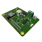
STM32WLE5JC Design Modification
Thought for 2 mins 16 sec
You want the STM32WLE5JC (LoRa‑E5) to be the only MCU, with SWD via Tag‑Connect, I2C/UART/one‑wire breakouts, solar+LiFePO4 power, and a 5 V output on a rectangular blue PCB.
Plan summary:
- Remove unused parts: U6, J1, J3, J6, 12.5 V boost rail (IC1, L1, D4, related passives), RS‑485 (IC2, related), and mounting holes H1/H2.
- Make U4 sole MCU; add Tag‑Connect TC2030 SWD pads (SWDIO, SWCLK, NRST, 3V3, GND; SWO optional); keep RF and J2.
- Power: add Solar+/Solar− pads; replace U2 with a LiFePO4 charger for 5 V input and 14430 cell; add Batt+/Batt− pads; ensure 3.3 V rail for STM32; add a 5 V boost converter and 5V_OUT pads.
- IO breakouts: add solder pads for I2C (SCL/SDA with pull‑ups), UART (TX/RX), and two GPIO for one‑wire (optional pull‑ups), plus nearby 3V3 and GND pads.
- PCB/layout: remove headers/holes; place new pads; connect nets; set rectangular outline and blue mask note; run ERC/DRC and availability checks.
This plan is ready to execute. Click Start to begin.
Before I proceed, two quick details to finalize:
- 5 V rail: what maximum continuous and peak current should we design for?
- One‑wire sensors: power at 3.3 V or 5 V? Do you want onboard 4.7 kΩ pull‑ups to that rail, or leave footprints unpopulated?
- Breakout style: edge castellated pads or interior rectangular solder pads (no headers)? Any preferred pad pitch/size?

Peak current on 5V rail will be 40mA. Continuous 30mA. One-wire sensors will need both 3.3v and 5v. Pads should be 2.54mm castellated.
Thought for 2 mins 7 sec
Your goal: single‑MCU STM32WLE5JC board with SWD, castellated IO, 5 V boost (30 mA cont/40 mA pk), and 5 V/60 mA solar + 14430 LiFePO4 power, on a rectangular blue PCB.
Plan:
- Remove legacy circuits and holes; keep LoRa‑E5 RF path.
- Redesign power: LiFePO4 charger (5 V solar), 3.3 V rail, 5 V boost, add Solar/Batt/5V pads.
- Add 6‑pad SWD, verify reset/decoupling.
- Add 2.54 mm castellated I2C (4.7 k pull‑ups, ≤ 400 pF), UART, two one‑wire with 3V3/5V/GND.
- Rectangular outline, blue mask; route and review.
Click Start to execute, or let me know if you want tweaks.
Pick 5V boost IC
Select LiFePO4 charger
Castellated pad guidance
One-wire pullup choice
Define breakout pin map