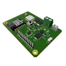
STM32WLE5JC Design Modification

You want the STM32WLE5JC (LoRa‑E5) to be the only MCU, with SWD via Tag‑Connect, I2C/UART/one‑wire breakouts, solar+LiFePO4 power, and a 5 V output on a rectangular blue PCB.
Plan summary:
  1. Remove unused parts: U6, J1, J3, J6, 12.5 V boost rail (IC1, L1, D4, related passives), RS‑485 (IC2, related), and mounting holes H1/H2.
  2. Make U4 sole MCU; add Tag‑Connect TC2030 SWD pads (SWDIO, SWCLK, NRST, 3V3, GND; SWO optional); keep RF and J2.
  3. Power: add Solar+/Solar− pads; replace U2 with a LiFePO4 charger for 5 V input and 14430 cell; add Batt+/Batt− pads; ensure 3.3 V rail for STM32; add a 5 V boost converter and 5V_OUT pads.
  4. IO breakouts: add solder pads for I2C (SCL/SDA with pull‑ups), UART (TX/RX), and two GPIO for one‑wire (optional pull‑ups), plus nearby 3V3 and GND pads.
  5. PCB/layout: remove headers/holes; place new pads; connect nets; set rectangular outline and blue mask note; run ERC/DRC and availability checks.
This plan is ready to execute. Click Start to begin.
Before I proceed, two quick details to finalize:
  • 5 V rail: what maximum continuous and peak current should we design for?
  • One‑wire sensors: power at 3.3 V or 5 V? Do you want onboard 4.7 kΩ pull‑ups to that rail, or leave footprints unpopulated?
  • Breakout style: edge castellated pads or interior rectangular solder pads (no headers)? Any preferred pad pitch/size?
Peak current on 5V rail will be 40mA. Continuous 30mA. One-wire sensors will need both 3.3v and 5v. Pads should be 2.54mm castellated.
Your goal: single‑MCU STM32WLE5JC board with SWD, castellated IO, 5 V boost (30 mA cont/40 mA pk), and 5 V/60 mA solar + 14430 LiFePO4 power, on a rectangular blue PCB.
Plan:
  1. Remove legacy circuits and holes; keep LoRa‑E5 RF path.
  2. Redesign power: LiFePO4 charger (5 V solar), 3.3 V rail, 5 V boost, add Solar/Batt/5V pads.
  3. Add 6‑pad SWD, verify reset/decoupling.
  4. Add 2.54 mm castellated I2C (4.7 k pull‑ups, ≤ 400 pF), UART, two one‑wire with 3V3/5V/GND.
  5. Rectangular outline, blue mask; route and review.
Click Start to execute, or let me know if you want tweaks.
Pick 5V boost IC
Select LiFePO4 charger
Castellated pad guidance
One-wire pullup choice
Define breakout pin map
What is this switch for?

Someone is typing...
17
what is the component supplier

Someone is typing...
64
please explain what U4 does.

Someone is typing...
79
design a simple robotic structure

Someone is typing...
28
please explain what IC1 does.

Someone is typing...
13
list all U3 pins in a table format. For each pin provide its pin number, pin nam...

Someone is typing...
36
A XIAO RP2040 tudja kezelni a 2 uart kapcsolatot?

Someone is typing...
77
recommend a replacement for U4.

Someone is typing...
6
what will be the ripple current in this capacitor?

Someone is typing...
50
please explain what +3V3 does.

Someone is typing...
7
how do I use Flux?

Someone is typing...
10
D4 purpose?

Someone is typing...
56
please explain what C6 does.

Someone is typing...
3
explain this project.

Someone is typing...
2
explain this project.

Someone is typing...
71
using the configuration of this project, what is the charging current?

Someone is typing...
72
please explain what R10 does.

Someone is typing...
74
are there any issues in this project?

Someone is typing...
26
recommend a replacement for U3.

Someone is typing...
35
list all ICs and the decoupling capacitors attached to each. Ensure to include a...

Someone is typing...
20
arduino

Someone is typing...
25
explain this project.

Someone is typing...
24
can you provide the BOM with description, maximum voltage that the component get...

Someone is typing...
63
please explain what R9, R6, R1, IC1, L1, D4, R4, VBAT, C10, SW1, 12\_5V, C7 do.

Someone is typing...
53
how do I use Flux?

Someone is typing...
54
create a high level mermaid block diagram of this project. Include key component...

Someone is typing...
60
please add LED with degree of view 30 degree with magenta color with 0402 footpr...

Someone is typing...
46
what is this design?

Someone is typing...
19
are there any issues in this project?

Someone is typing...
73
how to add lora communication?

Someone is typing...
45
please explain what U2 does.

Someone is typing...
51
Explain what each of the components here are, and what and where the connection...

Someone is typing...
70
please explain what D3 does.

Someone is typing...
12
explain this project.

Someone is typing...
14
scanner radio ?

Someone is typing...
15
why do you place here a resistor?

Someone is typing...
31
Hello, This is wrong. It is not like that from its datasheet

Someone is typing...
18
explain this project.

Someone is typing...
16
what kind of soldered patch antenna for lora would you advise instead of the ipe...

Someone is typing...
61
create a high level mermaid block diagram of U6. Include key component's manufac...

Someone is typing...
65
explain this project.

Someone is typing...
34
explain this project.

Someone is typing...
33
recommend a replacement for R5.

Someone is typing...
44
please explain what U4 does.

Someone is typing...
80
Tengo una bateria y su cargador, como puedo hacer un circuito para que la baterí...

Someone is typing...
32
list all ICs and the decoupling capacitors attached to each. Ensure to include a...

Someone is typing...
62
create a detailed step by step plan table for this project to verify its functio...

Someone is typing...
75
explain this project.

Someone is typing...
47
recommend a replacement for L2.

Someone is typing...
42
explain this project.

Someone is typing...
5
120ohm是如何計算出來的呢?

Someone is typing...
69
list all U2 pins in a table format. For each pin provide its pin number, pin nam...

Someone is typing...
76
please explain what D5 does.

Someone is typing...
37
recommend a replacement for U6.

Someone is typing...
11
recommend a replacement for U1.

Someone is typing...
43
add a adc circuit 5v

Someone is typing...
66
hi

Someone is typing...
9
+3V3
+3V3
+3V3
VSOLAR
VBAT
VBAT
+3V3
VBAT
+3V3
12_5V
VBAT
VSOLAR
VUSB
+3V3
J3
C11
Capacitance
4u7 F
U6
C1
Capacitance
10uF
VUSB
ENABLE
A
PIO2
SDA
PIO2
A
C4
Capacitance
4u7 F
SCL
+3V3
C2
Capacitance
10uF
C3
Capacitance
100nF
C8
Capacitance
68pF
+3V3
RX
NRST
RO
B
B
RX
NRST
TX
SDA
C10
Capacitance
22uF
PIO1
DI
C9
Capacitance
100nF
ENABLE
SCL
TX
C12
Capacitance
100nF
C7
Capacitance
22uF
PIO1
DI
12_5V
C6
Capacitance
100nF
C5
Capacitance
10uF
RO
R15
Resistance
4k7 Ω
R9
Resistance
20kΩ
R16
Resistance
4k7 Ω
R11
Resistance
22 Ω
R14
Resistance
120 Ω
R8
Resistance
2kΩ
R7
Resistance
15kΩ
R6
Resistance
150kΩ
R1
Resistance
3kΩ
R2
Resistance
1k5 Ω
R17
Resistance
4k7 Ω
R10
Resistance
22 Ω
R4
Resistance
4k7 Ω
R13
Resistance
470 Ω
R3
Resistance
68kΩ
R5
Resistance
6k8 Ω
R18
Resistance
22 Ω
U3
IC1
L1
Inductance
10uH
SW2
U4
L2
Inductance
2u2 H
D1
IC2
J1
U2
D4
D5
Color
Red
SW1
D2
Color
Green
J2
D3
J6
H2
H1
78
please explain what U4 does.

Someone is typing...
U1
22
please explain what U4 does.

@copilot please explain what U4 does.
2y
U4 is designated as the LoRa-E5 module manufactured by Seeed Technology Co., Ltd, with the manufacturer part number (MPN) 317990687. It is a compact and low-power module based on the STM32WLE5JC microcontroller, which combines both LoRa and sub-GHz radio communication capabilities. The module is designed for wireless communication in the sub-GHz band, making it suitable for long-range, low-power Internet of Things (IoT) applications. It supports the LoRaWAN protocol, which is widely used for deploying IoT networks.
Here are some of the key functionalities and pin connections of the U4 module:
  • VCC (Pin 1): Power supply for the module. It should be connected to a +3.3V power source.
  • GND (Pins 2, 14, 16, 22): Ground pins. These should be connected to the system ground.
  • Digital I/O Pins (Various, including PA13, PA14, PB15, etc.): These pins serve multiple functions, including digital input/output, interfacing with other devices, etc.
  • RFIO (Pin 15): The radio frequency input/output pin. It is used for connecting the module's RF transceiver to an antenna for sending and receiving LoRa signals.
  • RST (Pin 17): Reset pin. It is used to reset the module.
  • PA2, PA3, PA9, PA10 (Pins 18, 19, 21, 27): General purpose I/O pins that can be used for various functions based on the application requirements.
The LoRa-E5 module encapsulates the complexity of the LoRa physical layer. It enables easy integration into IoT devices, providing capabilities for sending and receiving data over long distances with low power consumption. This makes U4 highly suitable for applications such as environmental monitoring, smart agriculture, smart cities, and remote sensing, where wireless connectivity over wide areas is required without frequent battery replacements.
2y
Someone is typing...
23
please explain what U4 does.

@copilot please explain what U4 does.
2y
U4 in your project is the LoRa-E5 module from Seeed Studio, with the MPN (Manufacturer Part Number) 317990687. This module is based on the STM32WLE5JC microcontroller from STMicroelectronics, which integrates both a microcontroller and a LoRa transceiver into a single package. It's specifically designed for use in low-power wireless IoT (Internet of Things) devices.
Here's a breakdown of what U4 (LoRa-E5 module) does in your project:
  • Microcontroller Functionality: As a microcontroller unit (MCU), it executes the software that controls your device. This software can handle data from sensors, process it, and control other components like actuators. The STM32WLE5JC MCU at its core is based on an Arm Cortex-M4 processor, which offers a good balance between power efficiency and processing capability.
  • LoRa Connectivity: The module provides long-range, low-power wireless communication capabilities using the LoRa (Long Range) protocol. This is suitable for sending small amounts of data over long distances, which is typical in various IoT applications, especially those deployed in remote areas or requiring battery operation over extended periods.
  • I/O and Interface Options: Your project's description lists several pins on the U4 module, including digital I/O (Input/Output) pins (PA13, PA14, etc.), power supply pins (VCC, GND), and RF (radio frequency) interface pins (RFIO). These enable the module to interact with a wide range of peripheral devices and sensors, and to be powered efficiently.
  • Network Capabilities: By using LoRa technology, U4 is capable of connecting to LoRaWAN networks. LoRaWAN is a protocol for wide-area networks that allows low-power devices to communicate with Internet-connected applications over long-range wireless connections.
In summary, U4 serves as the heart of your "Green Dot 2040E5" Board, providing both the computing power to process data and the wireless capabilities to send this data over long distances using the LoRa network. This makes it an ideal choice for IoT applications that require remote sensing and control.
2y
Someone is typing...
48
what is the signal noise here?

what is the signal noise here?
2y
Someone is typing...
39
recommend a replacement for D4.

@copilot recommend a replacement for D4.
2y
To recommend a replacement for D4, which is originally specified as an SS34 Schottky diode, we need to consider a few key parameters that make it suitable for your application. The SS34 is known for its low forward voltage drop and fast switching speed. It is commonly used in applications requiring efficient voltage rectification at relatively high currents. Given these attributes and without specific requirements regarding package size or maximum reverse voltage, I'll assume typical requirements for IoT power management applications.
Recommended Replacement:
  • Part Number: 1N5822
  • Manufacturer: Various
  • Key Specifications:
    • Forward Current ($I_F$): Up to 3A, which is comparable to the SS34.
    • Forward Voltage Drop ($V_F$): Typically around 0.525V at 3A, which is efficient for power applications.
    • Maximum Reverse Voltage ($V_R$): 40V, providing a good overhead for most low to medium voltage applications.
    • Package: DO-201AD, which is a through-hole package. If a surface-mount package is required, similar specifications can be found in the SMC (DO-214AB) package.
    • Operation Junction Temperature: -65°C to 125°C, suitable for a wide range of environmental conditions.
Rationale for Recommendation:
  • The 1N5822 is chosen for its ability to handle similar currents as the SS34, its efficiency in terms of forward voltage drop, and its widespread availability from multiple manufacturers.
  • It offers robust performance for power rectification and is a popular choice in power supply and solar panel applications, aligning well with IoT and energy-harvesting contexts.
  • The suggested diode is versatile and readily available, making it a convenient choice for replacements or new designs.
Note: It's important to ensure the replacement diode meets the specific needs of your application, such as matching the footprint if a direct PCB replacement is needed, and handling the specific reverse voltage and forward current requirements of your circuit. The 1N5822 in a surface-mount package can be considered if compatibility with the existing footprint is critical.
Your application and existing design constraints could necessitate a different choice, so please review the specifications of the recommended replacement in the context of your specific use case.
2y
Someone is typing...
29
list all U4 pins in a table format. For each pin provide its pin number, pin nam...

@copilot list all U4 pins in a table format. For each pin provide its pin number, pin name and function.
2y
Here's a table listing all pins for U4 along with their pin numbers, names, and functions based on the provided excerpts:

Table


Pin NumberPin NameFunction
1VCCSupply voltage for the module
2GNDGround
3PA13SWDIO of SWIM for program download
4PA14SWCLK of SWIM for program download
5PB15SCL of I2C2 from MCU
6PA15SDA of I2C2 from MCU
7PB4MCU GPIO
8PB3MCU GPIO
9PB7UART1_RX from MCU
10PB6UART1_TX from MCU
11PB5MCU GPIO
12PC1MCU GPIO; LPUART1_TX from MCU
13PC0MCU GPIO; LPUART1_RX from MCU
14GNDGround
15RFIORF input/output
16GNDGround
17RSTReset trigger input for MCU
18PA3(Function not specified in the excerpts)
19PA2(Function not specified in the excerpts)
20PB10(Function not specified in the excerpts)
21PA9(Function not specified in the excerpts)
22GNDGround
23PA0(Function not specified in the excerpts)
24PB13(Function not specified in the excerpts)
25PB9(Function not specified in the excerpts)
26PB14(Function not specified in the excerpts)
27PA10(Function not specified in the excerpts)
28PB0(Function not specified in the excerpts)
This table is constructed from the details found in excerpts tied to MPN: 317990687. Functions for some pins are explicitly mentioned, while others were left unspecified in the provided excerpts.
2y
Someone is typing...
38
please explain what D5 does.

@copilot please explain what D5 does.
2y
Designator D5 is a light-emitting diode (LED) with the following characteristics:
  • MPN (Manufacturer Part Number): NCD0603R1
  • Color: Red
  • Forward Voltage: $2.0V$
  • Forward Current: $20mA$
  • Package: SMD, specifically the 0603 package
  • Manufacturer Name: Foshan NationStar Optoelectronics
  • License: Creative Commons Attribution 4.0 International License
In the context of the Green Dot 2040E5 Board, D5 can serve multiple purposes depending on how it's connected within the circuit. Typically, an LED like D5 could be used for:
  • Indicating Power: Shows whether the device is powered on.
  • Status Indicator: Signals the status of a process or operation, such as successful data transmission, errors, or other alerts.
  • Debugging: Helps in troubleshooting by indicating the reaching of certain points in the code or hardware operation.
Given the provided net connections of D5:
  • Cathode (P1) is connected to: The net including R2 (a resistor), which limits the current passing through D5 to prevent it from burning out.
  • Anode (P2) is connected to: The net connecting to U2's ~CHARG pin, suggesting that it might be used to indicate charging status if U2 is a charging IC.
Without other specific details on the intent in the schematic, it's safe to assume D5 plays a role in signaling some form of status related to the functionality tied to its connected nets. Given its connection to a charging-related pin, it could very well indicate charging status or completion on the Green Dot 2040E5 Board.
2y
Someone is typing...
40
list all ICs and the decoupling capacitors attached to each. Ensure to include a...

@copilot list all ICs and the decoupling capacitors attached to each. Ensure to include all ICs present in the design, including digital ICs, power converters, LDOs, etc. For every IC, clearly state:
  • What power net the decoupling capacitors are attached to. What is the stated voltage of that net.
  • The voltage rating and value of the attached decoupling capacitors.
  • Signal with the expression “[WARNING]” if any of the following conditions are met: no decoupling capacitors are attached; the voltage of the power net is higher than the voltage rating of the capacitor; No voltage range was stated for the capacitor. Give a separate “[WARNING]” for each condition. Signal with the expression “[OK]” if none of those conditions are met
  • Express the result in a markdown-formatted table
2y
Someone is typing...
21
are there any issues in this project?

@copilot are there any issues in this project?
2y
After carefully reviewing the schematic details of the "Green Dot 2040E5" Board project, here are some potential issues and considerations:
Power Supply and Management
  • Ensure proper decoupling capacitors are placed close to power supply pins of integrated circuits (ICs), such as U6 (XIAO RP2040) and U4 (LoRa-E5 module). Typically, a combination of capacitors (10uF and 100nF) near the power pins helps in filtering noise on the power supply lines.
  • The project includes solar charging capabilities through VSOLAR. It’s critical to verify that the solar panel's maximum output voltage and current match the input requirements of the solar charge controller (U2) to avoid damaging components.
  • Ensure there is a clear path for power distribution from the power sources (VBAT, VSOLAR, VUSB) to the loads while minimizing voltage drops and accounting for max current draw.
Signal Integrity and Routing
  • For critical communication lines such as those used for RS485 (RO, DI) and LoRa (U4: PB* pins), ensure trace impedance is controlled, and the routing minimizes cross-talk and electromagnetic interference (EMI).
  • I²C lines (SDA, SCL) should have proper pull-up resistors (typically 4.7kΩ), and these lines should be kept as short as possible to ensure reliable communication. It seems the project might already include related pull-up resistors (e.g., R15, R16) but double-check they are appropriately configured in the schematic for the I²C bus requirements.
Component Specifications and Placement
  • Review the ratings of voltage regulators (U3, U1) and ensure they meet the requirements for maximum input voltage and output current. Also, they should have appropriate heat dissipation measures if significant power is expected to flow through them.
  • The decoupling and bypass capacitors should be located as close as possible to their respective ICs power pins for optimal performance.
  • Confirm that all the polarized components (e.g., diodes D1, D3, D4, and electrolytic capacitors C10, C7) are correctly oriented in relation to their respective power supply lines.
General Checks
  • Verify that all nets intended for connection (e.g., GND, +3V3, VSOLAR, VBAT) are correctly and securely connected throughout the board, with no unintentionally floating connections.
  • Ensure all components have correct footprints matching their physical packages to avoid issues during PCB assembly.
  • Check for any unconnected pins (especially for ICs and modules) that should either be tied to a defined voltage level or configured according to the manufacturer's recommendation for stability.
These issues are based on common design considerations and best practices. The specific details of your application might necessitate different configurations. Please review datasheets and application notes for your components to confirm compatibility and correct usage.
2y
Someone is typing...
30
recommend a replacement for SW2.

@copilot recommend a replacement for SW2.
2y
To recommend a suitable replacement for switch SW2, which does not have detailed specifications provided in your project description, I'll assume standard requirements for a switch used in an electronic project like the "Green Dot 2040E5" board. Given its purpose and the common use cases in such boards, I'd recommend considering the following criteria for selecting a replacement:
  1. Switch Type: SPST (Single Pole Single Throw) or SPDT (Single Pole Double Throw), depending on the functionality required in your specific use case. If SW2 is used to simply open or close a circuit, an SPST would suffice. If it switches between two circuits, an SPDT is needed.
  2. Current and Voltage Rating: Ensure the replacement can handle the current and voltage levels in your circuit. For most low-power electronics projects like yours, switches rated for at least 50mA at 12VDC are often sufficient.
  3. Mounting Type: Depending on your board design and space constraints, you may choose between surface-mount (SMD) and through-hole (TH) mounting types. Your current design doesn't specify which type SW2 is, so please select according to your PCB layout and assembly preferences.
  4. Switching Mechanism: If SW2 is used frequently, consider a tactile pushbutton for a satisfying click feedback. For less frequent operations or reset functions, a slide or toggle switch could be appropriate.
  5. Size and Form Factor: Make sure the replacement switch fits the allocated space on your PCB. Pay attention to the switch dimensions and compare them with the footprint of SW2 in your design.
Given these general criteria and without specific details on the function and form factor of SW2 in your project, a generic recommendation would be:
  • For SPST: E-Switch's TL3301 series tactile switches for SMD applications, known for their reliability and small footprint.
  • For SPDT: C&K's Miniature Toggle Switches (part number 7101 series) for through-hole applications, offering durability and a wide variety of actuator options.
Please revise these recommendations based on SW2's specific role in your project and other constraints such as mounting preference and space availability on your PCB.
2y
Someone is typing...
59
create a high level mermaid block diagram of H2. Include key component's manufac...

@copilot create a high level mermaid block diagram of H2. Include key component's manufacturer part number in each block whenever possible.
2y
Creating a high-level block diagram in Mermaid syntax for the H2 component directly is not applicable since H2, based on your project description, is designated as a Mounting Hole (Designator Prefix: H) and does not directly interface with other components in an electronic or electrical manner. However, I can provide a high-level block diagram of key components and their connections in your project that are relevant to the overall operation of the "Green Dot 2040E5" board.
This diagram will illustrate the connections between major components like the XIAO RP2040 (U6), the LoRa-E5 module (U4), power management components including the solar charging IC (U2: CN3063) and key interfaces such as RS485 provided by IC2 (SP3481CN-L/TR).

Diagram


Rendering diagram...
Notes on the Diagram:
  • Power_Mgmt: Represents the collective power management system, including all power-related connections and components not listed with part numbers, like inductors or capacitors for power stabilization.
  • XIAO_RP2040: The core microcontroller unit providing the main logic and control functionality, including interfacing with sensors and communication modules.
  • LoRa_E5: The LoRa communication module used for connecting the device to the cloud or other LoRa-enabled devices.
  • RS485: Represents the RS485 transceiver for sensor connectivity.
  • SolarCharging: Points to the solar charge controller, which is part of the energy harvesting feature of the device, managing power coming from solar panels.
  • BatteryProtection and +3V3+3V3: Placeholder for battery protection circuits and the 3.3V power supply network respectively.
  • VBAT, VSOLAR: Represent the connections for battery voltage and solar panel input.
This diagram is simplified for a high-level overview and does not include every component or the detailed network of connections, focusing instead on major blocks and their interactions within the Green Dot 2040E5 board.
2y
Someone is typing...
49
plot this signal

@copilot plot this signal
2y
To assist you effectively, I'll need more specific information about the signal you're referring to. In the context of your project, a signal can be any electrical input or output - for example, an analog voltage level, a digital signal, or some waveform characteristic of either AC or DC currents.
If you can provide details such as:
  • The name or designation of the signal within your project.
  • Its expected behavior (e.g., is it a continuous waveform, a pulse, a digital signal transitioning between high and low states).
  • The conditions under which the signal should be plotted (e.g., under no load, under a specific load, during start-up, etc.).
  • The range of values you're interested in (e.g., voltage levels, currents, frequency).
With this information, I could provide a more targeted response or guide you on how to use tools within the Flux environment to simulate or visualize this signal.
2y
Someone is typing...
41
recommend a replacement for U4.

@copilot why there are only two mounting holes
2y
In your project, "The Green Dot 2040E5 Board," there are indeed only two mounting holes, designated as H1 and H2. This could be due to several reasons based on typical design considerations, but without specific design constraints or the physical size of the PCB being known, I'll outline some common reasons for choosing a smaller number of mounting holes:
  1. Size Constraints: The overall size of the PCB might be constrained due to the application it is designed for, which limits the space available for mounting holes.
  2. Component Density: The board might be densely packed with components, leaving limited space for additional mounting holes without risking interference with traces or components.
  3. Design Simplicity: Fewer mounting holes can simplify the design and assembly process, especially for small or lightweight boards where two points of support are sufficient for stability.
  4. Cost Considerations: Every additional feature, including mounting holes, adds complexity and potential cost to the PCB manufacturing process. Limiting the number of holes can help manage these costs.
  5. Flexibility in Mounting: Depending on the application, having fewer mounting points might offer more flexibility in how the board can be installed or fitted into a particular enclosure.
However, it's important to consider that having only two mounting points may affect the mechanical stability and resistance to vibration or stress, especially in harsh environments or applications subject to movement. If you find that more support points are needed for your application, you might reconsider the layout to accommodate additional mounting holes, ensuring not to compromise the electrical performance or interfere with critical component placements and traces.
If you have specific constraints or requirements that are influencing the number of mounting holes in your design, I could offer more tailored advice with that context.
2y
@copilot recommend a replacement for U4.
2y
Someone is typing...


  • Generic Inductor
    A generic fixed inductor suitable for rapid circuit topology development. The footprint automatically adapts based on the selected package, supporting standard SMD sizes (e.g., 0402, 0603, 0805) as well as well-known inductor packages such as SDR1806, PA4320, SRN6028, and SRR1260. Standard inductor values: 1.0 nH, 10 nH, 100 nH, 1.0 µH, 10 µH, 100 µH, 1.0 mH 1.2 nH, 12 nH, 120 nH, 1.2 µH, 12 µH, 120 µH, 1.2 mH 1.5 nH, 15 nH, 150 nH, 1.5 µH, 15 µH, 150 µH, 1.5 mH 1.8 nH, 18 nH, 180 nH, 1.8 µH, 18 µH, 180 µH, 1.8 mH 2.2 nH, 22 nH, 220 nH, 2.2 µH, 22 µH, 220 µH, 2.2 mH 2.7 nH, 27 nH, 270 nH, 2.7 µH, 27 µH, 270 µH, 2.7 mH 3.3 nH, 33 nH, 330 nH, 3.3 µH, 33 µH, 330 µH, 3.3 mH 3.9 nH, 39 nH, 390 nH, 3.9 µH, 39 µH, 390 µH, 3.9 mH 4.7 nH, 47 nH, 470 nH, 4.7 µH, 47 µH, 470 µH, 4.7 mH 5.6 nH, 56 nH, 560 nH, 5.6 µH, 56 µH, 560 µH, 5.6 mH 6.8 nH, 68 nH, 680 nH, 6.8 µH, 68 µH, 680 µH, 6.8 mH 8.2 nH, 82 nH, 820 nH, 8.2 µH, 82 µH, 820 µH, 8.2 mH #generics #CommonPartsLibrary
  • Generic Capacitor
    A generic fixed capacitor ideal for rapid circuit topology development. You can choose between polarized and non-polarized types, its symbol and the footprint will automatically adapt based on your selection. Supported options include standard SMD sizes for ceramic capacitors (e.g., 0402, 0603, 0805), SMD sizes for aluminum electrolytic capacitors, and through-hole footprints for polarized capacitors. Save precious design time by seamlessly add more information to this part (value, footprint, etc.) as it becomes available. Standard capacitor values: 1.0pF, 10pF, 100pF, 1000pF, 0.01uF, 0.1uF, 1.0uF, 10uF, 100uF, 1000uF, 10000uF 1.1pF, 11pF, 110pF, 1100pF 1.2pF, 12pF, 120pF, 1200pF 1.3pF, 13pF, 130pF, 1300pF 1.5pF, 15pF, 150pF, 1500pF, 0.015uF, 0.15uF, 1.5uF, 15uF, 150uF, 1500uF 1.6pF, 16pF, 160pF, 1600pF 1.8pF, 18pF, 180pF, 1800pF 2.0pF, 20pF, 200pF, 2000pF 2.2pF, 22pF, 220pF, 2200pF, 0.022uF, 0.22uF, 2.2uF, 22uF, 220uF, 2200uF 2.4pF, 24pF, 240pF, 2400pF 2.7pF, 27pF, 270pF, 2700pF 3.0pF, 30pF, 300pF, 3000pF 3.3pF, 33pF, 330pF, 3300pF, 0.033uF, 0.33uF, 3.3uF, 33uF, 330uF, 3300uF 3.6pF, 36pF, 360pF, 3600pF 3.9pF, 39pF, 390pF, 3900pF 4.3pF, 43pF, 430pF, 4300pF 4.7pF, 47pF, 470pF, 4700pF, 0.047uF, 0.47uF, 4.7uF, 47uF, 470uF, 4700uF 5.1pF, 51pF, 510pF, 5100pF 5.6pF, 56pF, 560pF, 5600pF 6.2pF, 62pF, 620pF, 6200pF 6.8pF, 68pF, 680pF, 6800pF, 0.068uF, 0.68uF, 6.8uF, 68uF, 680uF, 6800uF 7.5pF, 75pF, 750pF, 7500pF 8.2pF, 82pF, 820pF, 8200pF 9.1pF, 91pF, 910pF, 9100pF #generics #CommonPartsLibrary
  • Generic Resistor
    A generic fixed resistor ideal for rapid circuit topology development. Its footprint automatically adapts based on the selected package case code—supporting 0402, 0603, 0805, 1203, and many other standard SMD packages, as well as axial horizontal and vertical configurations. Save precious design time by seamlessly add more information to this part (value, footprint, etc.) as it becomes available. Standard resistor values: 1.0 ohm, 10 ohm, 100 ohm, 1.0k ohm, 10k ohm, 100k ohm, 1.0M ohm 1.1 ohm, 11 ohm, 110 ohm, 1.1k ohm, 11k ohm, 110k ohm, 1.1M ohm 1.2 ohm, 12 ohm, 120 ohm, 1.2k ohm, 12k ohm, 120k ohm, 1.2M ohm 1.3 ohm, 13 ohm, 130 ohm, 1.3k ohm, 13k ohm, 130k ohm, 1.3M ohm 1.5 ohm, 15 ohm, 150 ohm, 1.5k ohm, 15k ohm, 150k ohm, 1.5M ohm 1.6 ohm, 16 ohm, 160 ohm, 1.6k ohm, 16k ohm, 160k ohm, 1.6M ohm 1.8 ohm, 18 ohm, 180 ohm, 1.8K ohm, 18k ohm, 180k ohm, 1.8M ohm 2.0 ohm, 20 ohm, 200 ohm, 2.0k ohm, 20k ohm, 200k ohm, 2.0M ohm 2.2 ohm, 22 ohm, 220 ohm, 2.2k ohm, 22k ohm, 220k ohm, 2.2M ohm 2.4 ohm, 24 ohm, 240 ohm, 2.4k ohm, 24k ohm, 240k ohm, 2.4M ohm 2.7 ohm, 27 ohm, 270 ohm, 2.7k ohm, 27k ohm, 270k ohm, 2.7M ohm 3.0 ohm, 30 ohm, 300 ohm, 3.0K ohm, 30K ohm, 300K ohm, 3.0M ohm 3.3 ohm, 33 ohm, 330 ohm, 3.3k ohm, 33k ohm, 330k ohm, 3.3M ohm 3.6 ohm, 36 ohm, 360 ohm, 3.6k ohm, 36k ohm, 360k ohm, 3.6M ohm 3.9 ohm, 39 ohm, 390 ohm, 3.9k ohm, 39k ohm, 390k ohm, 3.9M ohm 4.3 ohm, 43 ohm, 430 ohm, 4.3k ohm, 43K ohm, 430K ohm, 4.3M ohm 4.7 ohm, 47 ohm, 470 ohm, 4.7k ohm, 47k ohm, 470k ohm, 4.7M ohm 5.1 ohm, 51 ohm, 510 ohm, 5.1k ohm, 51k ohm, 510k ohm, 5.1M ohm 5.6 ohm, 56 ohm, 560 ohm, 5.6k ohm, 56k ohm, 560k ohm, 5.6M ohm 6.2 ohm, 62 ohm, 620 ohm, 6.2k ohm, 62K ohm, 620K ohm, 6.2M ohm 6.8 ohm, 68 ohm, 680 ohm, 6.8k ohm, 68k ohm, 680k ohm, 6.8M ohm 7.5 ohm, 75 ohm, 750 ohm, 7.5k ohm, 75k ohm, 750k ohm, 7.5M ohm 8.2 ohm, 82 ohm, 820 ohm, 8.2k ohm, 82k ohm, 820k ohm, 8.2M ohm 9.1 ohm, 91 ohm, 910 ohm, 9.1k ohm, 91k ohm, 910k ohm, 9.1M ohm #generics #CommonPartsLibrary
  • Net Portal
    Wirelessly connects nets on schematic. Used to organize schematics and separate functional blocks. To wirelessly connect net portals, give them same designator. #portal
  • RMCF0805JT47K0
    General Purpose Thick Film Standard Power and High-Power Chip Resistor 47 kOhms ±5% 0.125W, 1/8W Chip Resistor 0805 (2012 Metric) Automotive AEC-Q200 Thick Film Features: - RMCF – standard power ratings - RMCP – high power ratings - Nickel barrier terminations standard - Power derating from 100% at 70ºC to zero at +155ºC - RoHS compliant, REACH compliant, and halogen free - AEC-Q200 compliant
  • 875105359001
    10 µF 16 V Aluminum - Polymer Capacitors Radial, Can - SMD 30mOhm 2000 Hrs @ 105°C #commonpartslibrary #capacitor #aluminumpolymer #radialcan
  • CTL1206FYW1T
    Yellow 595nm LED Indication - Discrete 1.7V 1206 (3216 Metric)
  • 1070TR
    Battery Holder (Open) Coin, 20.0mm 1 Cell SMD (SMT) Tab bate or batt #forLedBlink
  • Ground
    A common return path for electric current. Commonly known as ground.
  • Terminal
    Terminal
    An electrical connector acting as reusable interface to a conductor and creating a point where external circuits can be connected.

The Green Dot 2040E5 Board

The Green Dot 2040E5 Board thumbnail
The "Green Dot 2040E5" Board is a Node that interfaces RS485 Sensor probes and can log information to the cloud using LoRa Connectivity. It uses the XIAO RP2040 and the LoRa-E5 (STM32WLE5JC) modules from Seeed Studio to do its magic. It also has amazing power management capabilities (Solar charging, Battery protection, etc) that make it very useful for IoT applications #internetOfThings #smartHomeDevices #SeeedStudio #XIAO #LoRa #RP2040 #IoT

Layout Rules

mm

Yes

10mm

Top

deg

Properties

Properties describe core aspects of the project.

Pricing & Availability

Distributor

Qty 1

Arrow

$13.68–$36.95

Digi-Key

$13.01–$15.08

LCSC

$35.58–$36.70

Mouser

$16.26–$16.77

Verical

$5.02–$6.41

Controls