• 83 Keyboard

    83 Keyboard

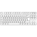
    A 83 key keyboard, Norwegian QWERTY/DVORAK ISO style. It's of course possible to use other languages, as the MX cherry switches will accept keycaps with whatever language you need. It uses 83 1N4148 diodes and three LED's for caps lock,scroll lock, and QWERTY/DVORAK. It also needs pin headers that accepts the pins from a Teensy++2.0

    adrian95

    4 years ago

    0 Uses

    5 Comments

    5 Stars


  • PIN_Headers_40

    PIN_Headers_40

    2x20 Pin Header (2mm pitch)

    6 months ago

    0 Uses

    0 Comments

    1 Star


  • MPXV7002DP

    MPXV7002DP

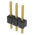
    Through Hole straight pin header, 01x03, 2.54mm pitch, single row #connector #pinheader #tht

    9 months ago

    0 Uses

    0 Comments

    1 Star


  • Pin Header 01x04 2.54mm Vertical

    Pin Header 01x04 2.54mm Vertical

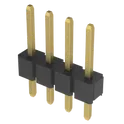
    Through Hole straight pin header, 01x04, 2.54mm pitch, single row #connector #pinheader #tht

    2 years ago

    0 Uses

    1 Comment

    0 Stars


  • Pin Header 01x08 2.54mm Vertical

    Pin Header 01x08 2.54mm Vertical

    Through Hole straight pin header, 01x08, 2.54mm pitch, single row #connector #pinheader #tht

    9 months ago

    0 Uses

    0 Comments

    0 Stars


  • Pin Header 01x10 2.54mm Vertical

    Pin Header 01x10 2.54mm Vertical

    Through Hole straight 15 pin header, 01x10, 2.54mm pitch, single row #pinheader #tht #SimplifiedFootprint

    2 years ago

    0 Uses

    0 Comments

    0 Stars


  • Pin Header 01x10 2.54mm Vertical

    Pin Header 01x10 2.54mm Vertical

    Through Hole straight pin header, 01x10, 2.54mm pitch, single row #pinheader #tht #SimplifiedFootprint

    3 years ago

    0 Uses

    0 Comments

    0 Stars


  • Pin Header Connector 02x03

    Pin Header Connector 02x03

    Form of electrical connector

    4 years ago

    0 Uses

    1 Comment

    0 Stars


  • PIN 02x06 2.54mm Vertical

    PIN 02x06 2.54mm Vertical

    Through Hole straight pin header, 02x06, 2.54mm pitch, double row #pinheader #tht #simplifiedFootprint

    2 years ago

    0 Uses

    3 Comments

    0 Stars


  • Arduino Mega 3pin PWM board

    Arduino Mega 3pin PWM board

    A board to use any PWM output with a 3 pin header

    2 years ago

    0 Uses

    16 Comments

    0 Stars


  • Connector 01x04 Horizontal

    Connector 01x04 Horizontal

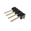
    Through hole straight pin header, 1x04, 4 pin, 4-pin, horizontal, angled, 2.54mm pitch, 6mm pin lenght single row

    0 Uses

    1 Comment

    0 Stars


  • FAKE_PUCK

    FAKE_PUCK

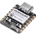
    Seeed Studio XIAO nRF54L15 Board (Pin Header Removed, JST-PH Battery, Pushbutton Added)

    8 months ago

    0 Uses

    0 Comments

    0 Stars


  • MS5611

    MS5611

    Through Hole straight pin header, 01x07, 2.54mm pitch, single row #connector #pinheader #tht

    9 months ago

    0 Uses

    0 Comments

    0 Stars


  • 2-pin_inline_analog_filter

    2-pin_inline_analog_filter

    Simple inline 2 pin header analog filter using common 603 sized components

    9 months ago

    0 Uses

    0 Comments

    0 Stars


  • V2 BTS796

    V2 BTS796

    Through Hole straight pin header, 02x06, 2.54mm pitch, double row #pinheader #tht #simplifiedFootprint

    2 years ago

    0 Uses

    0 Comments

    0 Stars


  • Connector 01x02 Vertical

    Connector 01x02 Vertical

    Through hole straight pin header, 1x02, 2 pin, 2-pin, vertical, 2.54mm pitch, 6mm pin lenght single row

    4 years ago

    0 Uses

    0 Comments

    0 Stars


  • Connector 01x04 Horizontal

    Connector 01x04 Horizontal

    Through hole straight pin header, 1x04, 4 pin, 4-pin, horizontal, angled, 2.54mm pitch, 6mm pin lenght single row

    2 years ago

    0 Uses

    0 Comments

    0 Stars


  • USB-C to SPI Breakout Board

    USB-C to SPI Breakout Board

    This is a USB type C female header to 6 pin pinout for SPI protocol. Do not use this for USB protocol. This is meant to be used with Scale Snap 3D to reduce RF noise across (max) 1 meter distance.

    2 years ago

    0 Uses

    0 Comments

    0 Stars


  • CMC to Ribbon Harness Interface

    CMC to Ribbon Harness Interface

    Interface board connecting a 64-pin TE CMC connector 2209129-1 to a 64-pin TE ribbon header 1-5102154-2 with straight-through pin mapping from pin 1 to pin 64.

    a month ago

    0 Uses

    0 Comments

    0 Stars


  • RFID-RC522

    RFID-RC522

    Datasheet-driven MFRC522 RFID reader PCB intended to replicate RC522 module behavior at 13.56 MHz with a 3.3 V nominal supply, 2.5 V to 3.3 V operating range, and RC522-style 8-pin host header compatibility. The MFRC522 datasheet is the authoritative source for pin usage, power rail relationships, oscillator requirements, reset/IRQ handling, and antenna interface topology. AVDD, DVDD, and TVDD must be tied to the same 3.3 V rail; PVDD must be equal to or lower than DVDD; unused MFIN must be tied to SVDD or PVSS; SVDD must be tied to a valid supply if not used independently. The design must use a 27.12 MHz crystal meeting CL 10 pF and ESR <= 100 ohms, local 100 nF decoupling on each MFRC522 supply grouping plus bulk capacitance, and an RF front-end based on the MFRC522 application diagram and reference reader matching/tuning network. PCB priorities are short crystal and RF connections, compact placement of decoupling capacitors at supply pins, solid ground reference, and protected antenna region with minimal digital routing through the RF area.

    +

    U
    U
    U
    U

    7 days ago

    0 Uses

    0 Comments

    0 Stars


  • BHI160B Reference design

    BHI160B Reference design

    This project is a reference design for the BHI160B sensor featuring an I2C interface with QWIIC and pin headers. The design includes decoupling capacitors and pull-up resistors for signal integrity. It's powered by a 3.3V supply. #referenceDesign #project #sensor #accelerometer #BHI160B #referenceDesign #imu #stm #template #reference-design

    +

    U

    2 years ago

    0 Uses

    15 Comments

    0 Stars


  • BHI160B Reference design

    BHI160B Reference design

    This project is a reference design for the BHI160B sensor featuring an I2C interface with QWIIC and pin headers. The design includes decoupling capacitors and pull-up resistors for signal integrity. It's powered by a 3.3V supply. #referenceDesign #project #sensor #accelerometer #BHI160B #referenceDesign #imu #stm #template #reference-design

    2 years ago

    0 Uses

    1 Comment

    0 Stars


  • network-audio-sink v1.0

    network-audio-sink v1.0

    Carrier board schematic for network-audio-sink v1.0 using plug-in dev board modules via pin headers plus selected on-board ICs. Initial net plan includes 5V_BUS, 3V3, GND, I2S0/I2S1 audio, SPI control, and Ethernet differential-pair nets.

    11 days ago

    0 Uses

    0 Comments

    0 Stars


  • KH-2PH90-1X12P-L10.5

    KH-2PH90-1X12P-L10.5

    Pin Headers KH-2PH90-1X12P-L10.5 HDR-TH_12P-P2.00-H-M-W7.2-N LCSC Part Number: C2938470 JLCPCB Part Class: Extended Part Manufactured by kinghelm(金航标)

    2 years ago

    0 Uses

    0 Comments

    0 Stars


  • Inherent Crimson Transporter

    Inherent Crimson Transporter

    SmartDeskPet v1.0 Shield Stage 1 status: - Goal: 5V input -> dual AMS1117-3.3 rails (+3V3_MCU and +3V3_WIFI) with common GND. - Note: Keep power nets explicitly named (avoid unnamed nets) to keep ERC happy. Stage 1 completion checklist: - Mark J1 Pin_1 (+5V) as a Power Output pin to satisfy ERC power-driver checks. - Verify all GND symbols/returns are on the same GND net. - Keep +5V_SERVO isolated from the main +5V net (only share GND). Stage 2 preparation notes (MPN/LCSC + layout constraints): - MPN/LCSC targets to define before Stage 2 exit: - AMS1117-3.3 (SOT-223): set exact MPN and (optionally) LCSC PN for both U1 and U2. - 100nF capacitor (0603): set MPN/LCSC for all 0603 100nF decouplers. - 4.7k resistor (0603): set MPN/LCSC for I2C pull-ups R1 and R2. - 1000uF bulk capacitor (radial): set MPN/LCSC for C7 (CP_Radial_D10.0mm_P5.00mm). - DC005 power jack/regulator input: select exact DC005 footprint + MPN/LCSC (if used). - 2.54mm headers/sockets: set MPN/LCSC for H1, H2, J1, J3, J4, J5, P3, P4, P5, and J2. - ESP-01S antenna keepout: - Reserve a copper keepout under and in front of the ESP-01S onboard antenna. - No copper pours/traces/components in the antenna region (top and bottom) per module guidelines. - H1/H2 header spacing: - Maintain 1000 mil spacing between H1 and H2 header centerlines (shield mechanical requirement). - Silkscreen placeholders: - Add silkscreen labels for: 5V IN, GND, +3V3_MCU, +3V3_WIFI, SERVO1, SERVO2, I2C SDA/SCL, DHT11, ASRPRO UART2, ESP-01S UART3. - Add placeholder text for: MPN, LCSC, board revision, and date code. Stage 3 layout constraints (placement and routing guidance): - Connector placement strategy: - Place H1 and H2 first to lock the shield mechanical interface; enforce 1000 mil spacing. - Place J1 and any DC005 input at the board edge for easy access. - Designated power area planning: - Group U1, U2, and C7 near the 5V entry point; keep high-current 5V and regulator loops short. - Use wide copper for +5V and any servo supply; stitch GND around power section. - Antenna keepout boundaries: - Place J2 (ESP-01S socket) at a board edge with the antenna facing outward. - Enforce a top-and-bottom copper keepout in the antenna region; keep noisy power traces away.

    5 months ago

    0 Uses

    0 Comments

    0 Stars


Page 1 of 2

Next