Part Information Review

  • Set VS's Pin Type to "Power In"
  • Set VS's Section to "Power"
  • Set VS's Pin Group to "VS"
  • Set VS's Pin Description to "Supply Input"
  • Set VS's Pin Orientation to "Top"
  • Set VS's Pin Type to "Power In"
  • Set VS's Section to "Power"
  • Set VS's Pin Group to "VS"
  • Set VS's Pin Description to "Supply Input"
  • Set VS's Pin Orientation to "Top"
  • Set VS's Pin Type to "Power In"
  • Set VS's Section to "Power"
  • Set VS's Pin Group to "VS"
  • Set VS's Pin Description to "Supply Input"
  • Set VS's Pin Orientation to "Top"
  • Set VOUT's Pin Type to "Power Out"
  • Set VOUT's Section to "Output"
  • Set VOUT's Pin Group to "VOUT"
  • Set VOUT's Pin Description to "Load Output"
  • Set VOUT's Pin Orientation to "Right"
  • Set VOUT's Pin Type to "Power Out"
  • Set VOUT's Section to "Output"
  • Set VOUT's Pin Group to "VOUT"
  • Set VOUT's Pin Description to "Load Output"
  • Set VOUT's Pin Orientation to "Right"
  • Set VOUT's Pin Type to "Power Out"
  • Set VOUT's Section to "Output"
  • Set VOUT's Pin Group to "VOUT"
  • Set VOUT's Pin Description to "Load Output"
  • Set VOUT's Pin Orientation to "Right"
  • Set GND's Pin Type to "Ground"
  • Set GND's Section to "Ground"
  • Set GND's Pin Group to "GND"
  • Set GND's Pin Description to "Device Ground"
  • Set GND's Pin Orientation to "Bottom"
  • Set GND's Pin Type to "Ground"
  • Set GND's Section to "Ground"
  • Set GND's Pin Group to "GND"
  • Set GND's Pin Description to "Thermal Ground Pad"
  • Set GND's Pin Orientation to "Bottom"
  • Set EN's Pin Type to "Input"
  • Set EN's Section to "Control"
  • Set EN's Pin Group to "Control"
  • Set EN's Pin Description to "Enable Input"
  • Set EN's Pin Orientation to "Left"
  • Set DIAG_EN's Pin Type to "Input"
  • Set DIAG_EN's Section to "Control"
  • Set DIAG_EN's Pin Group to "Control"
  • Set DIAG_EN's Pin Description to "Diagnostics Enable"
  • Set DIAG_EN's Pin Orientation to "Left"
  • Set LATCH's Pin Type to "Input"
  • Set LATCH's Section to "Control"
  • Set LATCH's Pin Group to "Control"
  • Set LATCH's Pin Description to "Latch Control"
  • Set LATCH's Pin Orientation to "Left"
  • Set ILIM's Pin Type to "Input"
  • Set ILIM's Section to "Control"
  • Set ILIM's Pin Group to "Control"
  • Set ILIM's Pin Description to "Current Limit Set"
  • Set ILIM's Pin Orientation to "Left"
  • Set *FAULT's Pin Type to "Output"
  • Set *FAULT's Section to "Diagnostic"
  • Set *FAULT's Pin Group to "Diagnostic"
  • Set *FAULT's Pin Description to "Fault Indicator"
  • Set *FAULT's Pin Orientation to "Right"
  • Set SNS's Pin Type to "Output"
  • Set SNS's Section to "Diagnostic"
  • Set SNS's Pin Group to "Diagnostic"
  • Set SNS's Pin Description to "Current Sense Output"
  • Set SNS's Pin Orientation to "Right"
  • Set NC's Pin Type to "Not Connected"
  • Set NC's Section to "No Connect"
  • Set NC's Pin Group to "NC"
  • Set NC's Pin Description to "No Connect"
  • Set NC's Pin Orientation to "Right"
*FAULT
Pin Number
4
VS
Pin Number
13
VOUT
Pin Number
8
LATCH
Pin Number
5
DIAG_EN
Pin Number
3
VS
Pin Number
12
GND
Pin Number
15
ILIM
Pin Number
7
VS
Pin Number
14
NC
Pin Number
11
SNS
Pin Number
6
GND
Pin Number
1
VOUT
Pin Number
9
VOUT
Pin Number
10
EN
Pin Number
2


  • Generic Inductor
    A generic fixed inductor suitable for rapid circuit topology development. The footprint automatically adapts based on the selected package, supporting standard SMD sizes (e.g., 0402, 0603, 0805) as well as well-known inductor packages such as SDR1806, PA4320, SRN6028, and SRR1260. Standard inductor values: 1.0 nH, 10 nH, 100 nH, 1.0 µH, 10 µH, 100 µH, 1.0 mH 1.2 nH, 12 nH, 120 nH, 1.2 µH, 12 µH, 120 µH, 1.2 mH 1.5 nH, 15 nH, 150 nH, 1.5 µH, 15 µH, 150 µH, 1.5 mH 1.8 nH, 18 nH, 180 nH, 1.8 µH, 18 µH, 180 µH, 1.8 mH 2.2 nH, 22 nH, 220 nH, 2.2 µH, 22 µH, 220 µH, 2.2 mH 2.7 nH, 27 nH, 270 nH, 2.7 µH, 27 µH, 270 µH, 2.7 mH 3.3 nH, 33 nH, 330 nH, 3.3 µH, 33 µH, 330 µH, 3.3 mH 3.9 nH, 39 nH, 390 nH, 3.9 µH, 39 µH, 390 µH, 3.9 mH 4.7 nH, 47 nH, 470 nH, 4.7 µH, 47 µH, 470 µH, 4.7 mH 5.6 nH, 56 nH, 560 nH, 5.6 µH, 56 µH, 560 µH, 5.6 mH 6.8 nH, 68 nH, 680 nH, 6.8 µH, 68 µH, 680 µH, 6.8 mH 8.2 nH, 82 nH, 820 nH, 8.2 µH, 82 µH, 820 µH, 8.2 mH #generics #CommonPartsLibrary
  • Generic Capacitor
    A generic fixed capacitor ideal for rapid circuit topology development. You can choose between polarized and non-polarized types, its symbol and the footprint will automatically adapt based on your selection. Supported options include standard SMD sizes for ceramic capacitors (e.g., 0402, 0603, 0805), SMD sizes for aluminum electrolytic capacitors, and through-hole footprints for polarized capacitors. Save precious design time by seamlessly add more information to this part (value, footprint, etc.) as it becomes available. Standard capacitor values: 1.0pF, 10pF, 100pF, 1000pF, 0.01uF, 0.1uF, 1.0uF, 10uF, 100uF, 1000uF, 10000uF 1.1pF, 11pF, 110pF, 1100pF 1.2pF, 12pF, 120pF, 1200pF 1.3pF, 13pF, 130pF, 1300pF 1.5pF, 15pF, 150pF, 1500pF, 0.015uF, 0.15uF, 1.5uF, 15uF, 150uF, 1500uF 1.6pF, 16pF, 160pF, 1600pF 1.8pF, 18pF, 180pF, 1800pF 2.0pF, 20pF, 200pF, 2000pF 2.2pF, 22pF, 220pF, 2200pF, 0.022uF, 0.22uF, 2.2uF, 22uF, 220uF, 2200uF 2.4pF, 24pF, 240pF, 2400pF 2.7pF, 27pF, 270pF, 2700pF 3.0pF, 30pF, 300pF, 3000pF 3.3pF, 33pF, 330pF, 3300pF, 0.033uF, 0.33uF, 3.3uF, 33uF, 330uF, 3300uF 3.6pF, 36pF, 360pF, 3600pF 3.9pF, 39pF, 390pF, 3900pF 4.3pF, 43pF, 430pF, 4300pF 4.7pF, 47pF, 470pF, 4700pF, 0.047uF, 0.47uF, 4.7uF, 47uF, 470uF, 4700uF 5.1pF, 51pF, 510pF, 5100pF 5.6pF, 56pF, 560pF, 5600pF 6.2pF, 62pF, 620pF, 6200pF 6.8pF, 68pF, 680pF, 6800pF, 0.068uF, 0.68uF, 6.8uF, 68uF, 680uF, 6800uF 7.5pF, 75pF, 750pF, 7500pF 8.2pF, 82pF, 820pF, 8200pF 9.1pF, 91pF, 910pF, 9100pF #generics #CommonPartsLibrary
  • Generic Resistor
    A generic fixed resistor ideal for rapid circuit topology development. Its footprint automatically adapts based on the selected package case code—supporting 0402, 0603, 0805, 1203, and many other standard SMD packages, as well as axial horizontal and vertical configurations. Save precious design time by seamlessly add more information to this part (value, footprint, etc.) as it becomes available. Standard resistor values: 1.0 ohm, 10 ohm, 100 ohm, 1.0k ohm, 10k ohm, 100k ohm, 1.0M ohm 1.1 ohm, 11 ohm, 110 ohm, 1.1k ohm, 11k ohm, 110k ohm, 1.1M ohm 1.2 ohm, 12 ohm, 120 ohm, 1.2k ohm, 12k ohm, 120k ohm, 1.2M ohm 1.3 ohm, 13 ohm, 130 ohm, 1.3k ohm, 13k ohm, 130k ohm, 1.3M ohm 1.5 ohm, 15 ohm, 150 ohm, 1.5k ohm, 15k ohm, 150k ohm, 1.5M ohm 1.6 ohm, 16 ohm, 160 ohm, 1.6k ohm, 16k ohm, 160k ohm, 1.6M ohm 1.8 ohm, 18 ohm, 180 ohm, 1.8K ohm, 18k ohm, 180k ohm, 1.8M ohm 2.0 ohm, 20 ohm, 200 ohm, 2.0k ohm, 20k ohm, 200k ohm, 2.0M ohm 2.2 ohm, 22 ohm, 220 ohm, 2.2k ohm, 22k ohm, 220k ohm, 2.2M ohm 2.4 ohm, 24 ohm, 240 ohm, 2.4k ohm, 24k ohm, 240k ohm, 2.4M ohm 2.7 ohm, 27 ohm, 270 ohm, 2.7k ohm, 27k ohm, 270k ohm, 2.7M ohm 3.0 ohm, 30 ohm, 300 ohm, 3.0K ohm, 30K ohm, 300K ohm, 3.0M ohm 3.3 ohm, 33 ohm, 330 ohm, 3.3k ohm, 33k ohm, 330k ohm, 3.3M ohm 3.6 ohm, 36 ohm, 360 ohm, 3.6k ohm, 36k ohm, 360k ohm, 3.6M ohm 3.9 ohm, 39 ohm, 390 ohm, 3.9k ohm, 39k ohm, 390k ohm, 3.9M ohm 4.3 ohm, 43 ohm, 430 ohm, 4.3k ohm, 43K ohm, 430K ohm, 4.3M ohm 4.7 ohm, 47 ohm, 470 ohm, 4.7k ohm, 47k ohm, 470k ohm, 4.7M ohm 5.1 ohm, 51 ohm, 510 ohm, 5.1k ohm, 51k ohm, 510k ohm, 5.1M ohm 5.6 ohm, 56 ohm, 560 ohm, 5.6k ohm, 56k ohm, 560k ohm, 5.6M ohm 6.2 ohm, 62 ohm, 620 ohm, 6.2k ohm, 62K ohm, 620K ohm, 6.2M ohm 6.8 ohm, 68 ohm, 680 ohm, 6.8k ohm, 68k ohm, 680k ohm, 6.8M ohm 7.5 ohm, 75 ohm, 750 ohm, 7.5k ohm, 75k ohm, 750k ohm, 7.5M ohm 8.2 ohm, 82 ohm, 820 ohm, 8.2k ohm, 82k ohm, 820k ohm, 8.2M ohm 9.1 ohm, 91 ohm, 910 ohm, 9.1k ohm, 91k ohm, 910k ohm, 9.1M ohm #generics #CommonPartsLibrary
  • Ground
    A common return path for electric current. Commonly known as ground.
  • Terminal
    Terminal
    An electrical connector acting as reusable interface to a conductor and creating a point where external circuits can be connected.
  • Net Portal
    Wirelessly connects nets on schematic. Used to organize schematics and separate functional blocks. To wirelessly connect net portals, give them same designator. #portal
  • RMCF0805JT47K0
    General Purpose Thick Film Standard Power and High-Power Chip Resistor 47 kOhms ±5% 0.125W, 1/8W Chip Resistor 0805 (2012 Metric) Automotive AEC-Q200 Thick Film Features: - RMCF – standard power ratings - RMCP – high power ratings - Nickel barrier terminations standard - Power derating from 100% at 70ºC to zero at +155ºC - RoHS compliant, REACH compliant, and halogen free - AEC-Q200 compliant
  • 875105359001
    10 µF 16 V Aluminum - Polymer Capacitors Radial, Can - SMD 30mOhm 2000 Hrs @ 105°C #commonpartslibrary #capacitor #aluminumpolymer #radialcan
  • CTL1206FYW1T
    Yellow 595nm LED Indication - Discrete 1.7V 1206 (3216 Metric)
  • 1070TR
    Battery Holder (Open) Coin, 20.0mm 1 Cell SMD (SMT) Tab bate or batt #forLedBlink

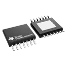
TPS1HTC30-Q1

TPS1HTC30-Q1 thumbnail
Automotive, 60-V, 6-A, 30-mΩ, one-channel smart high-side switch with adjustable current limit
TPS1HTC30-Q1 is a single-channel, smart high-side switch, with integrated NMOS power FET and charge pump, designed to meet the requirements of 24-V automotive battery systems. The low RON(30 mΩ) minimizes device power dissipation driving a wide range of output load current up to 6-A DC, and the 60- V DC operating range improves system robustness. The device integrates protection features such as thermal shutdown, output clamp, and current limit. These features improve system robustness during fault events such as short circuit. TPS1HTC30-Q1 implements an adjustable current limiting circuit that improves the reliability of the system by reducing inrush current when driving large capacitive loads and minimizing overload current. The device also provides an accurate load current sense that allows for improved load diagnostics such as overload and open-load detection enabling better predictive maintenance. TPS1HTC30-Q1 is available in a small 14-pin, 4.40- mm × 5.0-mm HTSSOP leaded package with 0.65- mm pin pitch minimizing the PCB footprint.
• Single-channel smart high-side power switch for 24-V automotive systems with full diagnostics • Wide operating voltage range: 6 V to 60 V – OVP protection: 66 V • Low RON: 30-mΩ typical, 55-mΩ maximum • Low standby current: < 0.5 µA • Low quiescent current (Iq): < 2 mA • Improve system level reliability through adjustable current limiting – Current limit: 2 A –16 A • Accurate current sensing: ±4% at 1 A • Protection – Overload and short-circuit protection – Integrated inductive discharge clamp – Undervoltage lockout (UVLO) protection – Loss of GND, loss of supply protection – Reverse battery protection with external components • Diagnostics – On and off state output open-load and short-tobattery detection – Overload and short to ground detection – Absolute and relative thermal shutdown detection • Functional Safety-Capable – Documentation available to aid functional safety system design • Operating junction temperature: –40 to 125°C • Input control: 1.8-V, 3.3-V and 5-V logic compatible • Integrated fault sense voltage scaling for ADC protection • Qualifications – AEC-Q100 qualified for automotive applications • Temperature grade 1: –40°C to +125°C, TA • 14-pin thermally-enhanced TSSOP package TPS1HTC30AQPWPRQ1

Properties

TPS1HTC30AQPWPRQ1

Texas Instruments

Integrated Circuit

IC

parametric-v1

Pricing & Availability

See prices from popular manufacturers for your project.

Controls