Part Information Review and Verification

2:39

Read TPS259814ARPWR datasheet for recommended operating conditions input v.

Read TPS259814ARPWR datasheet for thermal information package R-PW HTSSOP .

Read TPS259814ARPWR datasheet for features description 2.7 V to 16 V 10 A .

Read schematic.

Read layout.

Thought for a moment

Thought for a moment

Thought for a moment

Thought for a moment

Thought for a moment

Thought for a moment

Thought for a moment

Thought for a moment

Thought for a moment

Thought for a moment

Thought for a moment

Thought for a moment

Thought for a moment

Thought for a moment

Thought for a moment

Thought for a moment

Thought for a moment

Thought for a moment

Thought for a moment

Thought for a moment

Thought for a moment

Thought for a moment

Thought for a moment

Thought for a moment

Thought for a moment

Thought for a moment

Thought for a moment

Thought for a moment

Thought for a moment

Thought for a moment

Thought for a moment

Thought for a moment

Thought for a moment

Thought for a moment

Thought for a moment

Thought for a moment

Thought for a moment

Thought for a moment

Thought for a moment

Thought for a moment

Thought for a moment

Thought for a moment

Thought for a moment

Thought for a moment

Thought for a moment

Thought for a moment

Thought for a moment

Thought for a moment

Thought for a moment

Thought for a moment

Thought for a moment

Thought for a moment

Thought for a moment

Thought for a moment

Thought for a moment

Thought for a moment

Thought for a moment

Thought for a moment

Thought for a moment

Thought for a moment

Thought for a moment

Thought for a moment

Thought for a moment

Thought for a moment

Thought for a moment

Thought for a moment

Thought for a moment

Thought for a moment

Thought for a moment

Thought for a moment

Thought for a moment

Thought for a moment

Thought for a moment

Thought for a moment

Thought for a moment

Thought for a moment

Thought for a moment

Thought for a moment

Thought for a moment

Thought for a moment

Thought for a moment

Thought for a moment

Thought for a moment

Thought for a moment

Thought for a moment

Thought for 10 sec

Read "Extract TPS259814ARPWR metadata: manufacturer, full part number, package, pin count, device description, key specs including input voltage range current and operating temperature." in ti.com.

Read "Extract complete pin table for R-PW package: pin number, pin name, function/description for all pins including PowerPAD or thermal pad." in ti.com.

Read "Find package information and mechanical data for TPS259814ARPWR R-PW HTSSOP package, pin count and package code." in ti.com.

Read "Find key application notes, recommended operating conditions, absolute maximum ratings, transient overcurrent blanking timer, current limit, dVdt, EN UVLO OVLO, PG, FLT pin functions." in ti.com.

Read ti.com.

Read ti.com.

Read ti.com.

Read ti.com.

Found 1 results for TPS259814ARPWR datasheet pin description pinout R-PW package 14 pin.

I found critical mismatches: this part is officially a 10-pin TI RPW/VQFN-HR eFuse, but the current symbol/footprint exposes 14 terminals/pads, the package property is set to TO, and all pin types are still Unspecified. Full review is in the TPS259814ARPWR Part Review project file.

Created project doc "TPS259814ARPWR Part Review"

Looking at the datasheet of this component, can you group together pins by their functions? for example for Power, 3v3, gnd_1 gnd_2 etc NOTE: If you group them, can you not add the same pin if you already added them in a group? You should know which pin function is common for its function

2:19

Thought for a moment

Thought for a moment

Thought for a moment

Thought for a moment

Thought for a moment

Thought for a moment

Thought for a moment

Thought for a moment

Thought for a moment

Thought for a moment

Thought for a moment

Thought for a moment

Thought for a moment

Thought for a moment

Thought for a moment

Thought for a moment

Thought for a moment

Thought for a moment

Thought for a moment

Thought for a moment

Thought for a moment

Thought for a moment

Thought for a moment

Thought for a moment

Thought for a moment

Thought for 7 sec

Thought for a moment

Thought for a moment

Thought for a moment

Thought for a moment

Thought for a moment

Thought for a moment

Thought for a moment

Thought for a moment

Thought for a moment

Thought for a moment

Thought for a moment

Thought for a moment

Thought for a moment

Thought for a moment

Thought for a moment

Thought for a moment

Thought for a moment

Thought for a moment

Thought for a moment

Thought for a moment

Thought for a moment

Thought for a moment

Thought for a moment

Thought for a moment

Thought for a moment

Thought for a moment

Thought for a moment

Thought for a moment

Thought for a moment

Thought for a moment

Thought for a moment

Thought for a moment

Thought for 2 sec

Thought for a moment

Thought for a moment

Thought for a moment

Thought for a moment

Thought for a moment

Thought for a moment

Thought for a moment

Thought for a moment

Thought for a moment

Thought for a moment

Thought for a moment

Thought for a moment

Thought for a moment

Thought for a moment

Thought for a moment

Thought for a moment

Thought for a moment

Thought for a moment

Thought for a moment

Thought for a moment

Thought for a moment

Thought for a moment

Thought for a moment

Thought for a moment

Thought for a moment

Thought for a moment

Thought for a moment

Thought for a moment

Thought for a moment

Thought for a moment

Thought for a moment

Thought for a moment

Thought for a moment

Thought for a moment

Thought for a moment

Thought for a moment

Thought for a moment

Thought for a moment

Thought for a moment

Thought for a moment

Read schematic.

Grouped the valid TPS259814ARPWR datasheet pins 1–10 by function and updated their Pin Type, Section, Pin Group, Pin Description, and Pin Orientation. I intentionally did not group the extra duplicate terminals EN/UVLO_2, ~FLT_2, DVDT_2, and ITIMER_2 because they are pins 11–14, which do not exist on the official 10-pin RPW package and should be removed or fixed separately.
Remove invalid terminals
Run ERC check
Review pin groups
Recheck datasheet pins

Set Pin Type to "Input" on EN/UVLO_1 and ~EN~/OVLO, Set Pin Description to "Enable UVLO input" on EN/UVLO_1, and 34 more changes

Set EN/UVLO_1's Pin Type to "Input"

Set EN/UVLO_1's Pin Description to "Enable UVLO input"

Set EN/UVLO_1's Section to "Control"

Set EN/UVLO_1's Pin Group to "Enable_UVLO"

Set EN/UVLO_1's Pin Orientation to "Left"

Set ~EN~/OVLO's Pin Type to "Input"

Set ~EN~/OVLO's Pin Description to "Enable OVLO input"

Set ~EN~/OVLO's Section to "Control"

Set ~EN~/OVLO's Pin Group to "Enable_OVLO"

Set ~EN~/OVLO's Pin Orientation to "Left"

Set PG's Pin Type to "Open Collector"

Set PG's Pin Description to "Power-good output"

Set PG's Section to "Status"

Set PG's Pin Group to "Status"

Set PG's Pin Orientation to "Right"

Set ~FLT_1's Pin Type to "Open Collector"

Set ~FLT_1's Pin Description to "Fault indicator output"

Set ~FLT_1's Section to "Status"

Set ~FLT_1's Pin Group to "Status"

Set ~FLT_1's Pin Orientation to "Right"

Set IN's Pin Type to "Power In"

Set IN's Pin Description to "Power input"

Set IN's Section to "Power"

Set IN's Pin Group to "Power_Input"

Set IN's Pin Orientation to "Top"

Set OUT's Pin Type to "Power Out"

Set OUT's Pin Description to "Protected power output"

Set OUT's Section to "Power"

Set OUT's Pin Group to "Power_Output"

Set OUT's Pin Orientation to "Right"

Set DVDT_1's Pin Type to "Passive"

Set DVDT_1's Pin Description to "Slew-rate capacitor"

Set DVDT_1's Section to "Configuration"

Set DVDT_1's Pin Group to "Slew_Rate"

Set DVDT_1's Pin Orientation to "Left"

Set GND's Pin Type to "Ground"

Set GND's Pin Description to "Ground reference"

Set GND's Section to "Ground"

Set GND's Pin Group to "Ground"

Set GND's Pin Orientation to "Bottom"

Set ILM's Pin Type to "Output"

Set ILM's Pin Description to "Current-limit monitor"

Set ILM's Section to "Monitor_Configuration"

Set ILM's Pin Group to "Current_Limit_Monitor"

Set ILM's Pin Orientation to "Right"

Set ITIMER_1's Pin Type to "Passive"

Set ITIMER_1's Pin Description to "Blanking timer capacitor"

Set ITIMER_1's Section to "Configuration"

Set ITIMER_1's Pin Group to "Timer"

Set ITIMER_1's Pin Orientation to "Left"

Finished working

GND
Pin Number
8
EN/UVLO_2
Pin Number
11
PG
Pin Number
3
DVDT_1
Pin Number
7
ILM
Pin Number
9
EN/UVLO_1
Pin Number
1
~FLT_2
Pin Number
12
ITIMER_1
Pin Number
10
OUT
Pin Number
6
~EN~/OVLO
Pin Number
2
DVDT_2
Pin Number
13
IN
Pin Number
5
~FLT_1
Pin Number
4
ITIMER_2
Pin Number
14


  • Generic Inductor
    A generic fixed inductor suitable for rapid circuit topology development. The footprint automatically adapts based on the selected package, supporting standard SMD sizes (e.g., 0402, 0603, 0805) as well as well-known inductor packages such as SDR1806, PA4320, SRN6028, and SRR1260. Standard inductor values: 1.0 nH, 10 nH, 100 nH, 1.0 µH, 10 µH, 100 µH, 1.0 mH 1.2 nH, 12 nH, 120 nH, 1.2 µH, 12 µH, 120 µH, 1.2 mH 1.5 nH, 15 nH, 150 nH, 1.5 µH, 15 µH, 150 µH, 1.5 mH 1.8 nH, 18 nH, 180 nH, 1.8 µH, 18 µH, 180 µH, 1.8 mH 2.2 nH, 22 nH, 220 nH, 2.2 µH, 22 µH, 220 µH, 2.2 mH 2.7 nH, 27 nH, 270 nH, 2.7 µH, 27 µH, 270 µH, 2.7 mH 3.3 nH, 33 nH, 330 nH, 3.3 µH, 33 µH, 330 µH, 3.3 mH 3.9 nH, 39 nH, 390 nH, 3.9 µH, 39 µH, 390 µH, 3.9 mH 4.7 nH, 47 nH, 470 nH, 4.7 µH, 47 µH, 470 µH, 4.7 mH 5.6 nH, 56 nH, 560 nH, 5.6 µH, 56 µH, 560 µH, 5.6 mH 6.8 nH, 68 nH, 680 nH, 6.8 µH, 68 µH, 680 µH, 6.8 mH 8.2 nH, 82 nH, 820 nH, 8.2 µH, 82 µH, 820 µH, 8.2 mH #generics #CommonPartsLibrary
  • Generic Capacitor
    A generic fixed capacitor ideal for rapid circuit topology development. You can choose between polarized and non-polarized types, its symbol and the footprint will automatically adapt based on your selection. Supported options include standard SMD sizes for ceramic capacitors (e.g., 0402, 0603, 0805), SMD sizes for aluminum electrolytic capacitors, and through-hole footprints for polarized capacitors. Save precious design time by seamlessly add more information to this part (value, footprint, etc.) as it becomes available. Standard capacitor values: 1.0pF, 10pF, 100pF, 1000pF, 0.01uF, 0.1uF, 1.0uF, 10uF, 100uF, 1000uF, 10000uF 1.1pF, 11pF, 110pF, 1100pF 1.2pF, 12pF, 120pF, 1200pF 1.3pF, 13pF, 130pF, 1300pF 1.5pF, 15pF, 150pF, 1500pF, 0.015uF, 0.15uF, 1.5uF, 15uF, 150uF, 1500uF 1.6pF, 16pF, 160pF, 1600pF 1.8pF, 18pF, 180pF, 1800pF 2.0pF, 20pF, 200pF, 2000pF 2.2pF, 22pF, 220pF, 2200pF, 0.022uF, 0.22uF, 2.2uF, 22uF, 220uF, 2200uF 2.4pF, 24pF, 240pF, 2400pF 2.7pF, 27pF, 270pF, 2700pF 3.0pF, 30pF, 300pF, 3000pF 3.3pF, 33pF, 330pF, 3300pF, 0.033uF, 0.33uF, 3.3uF, 33uF, 330uF, 3300uF 3.6pF, 36pF, 360pF, 3600pF 3.9pF, 39pF, 390pF, 3900pF 4.3pF, 43pF, 430pF, 4300pF 4.7pF, 47pF, 470pF, 4700pF, 0.047uF, 0.47uF, 4.7uF, 47uF, 470uF, 4700uF 5.1pF, 51pF, 510pF, 5100pF 5.6pF, 56pF, 560pF, 5600pF 6.2pF, 62pF, 620pF, 6200pF 6.8pF, 68pF, 680pF, 6800pF, 0.068uF, 0.68uF, 6.8uF, 68uF, 680uF, 6800uF 7.5pF, 75pF, 750pF, 7500pF 8.2pF, 82pF, 820pF, 8200pF 9.1pF, 91pF, 910pF, 9100pF #generics #CommonPartsLibrary
  • Generic Resistor
    A generic fixed resistor ideal for rapid circuit topology development. Its footprint automatically adapts based on the selected package case code—supporting 0402, 0603, 0805, 1203, and many other standard SMD packages, as well as axial horizontal and vertical configurations. Save precious design time by seamlessly add more information to this part (value, footprint, etc.) as it becomes available. Standard resistor values: 1.0 ohm, 10 ohm, 100 ohm, 1.0k ohm, 10k ohm, 100k ohm, 1.0M ohm 1.1 ohm, 11 ohm, 110 ohm, 1.1k ohm, 11k ohm, 110k ohm, 1.1M ohm 1.2 ohm, 12 ohm, 120 ohm, 1.2k ohm, 12k ohm, 120k ohm, 1.2M ohm 1.3 ohm, 13 ohm, 130 ohm, 1.3k ohm, 13k ohm, 130k ohm, 1.3M ohm 1.5 ohm, 15 ohm, 150 ohm, 1.5k ohm, 15k ohm, 150k ohm, 1.5M ohm 1.6 ohm, 16 ohm, 160 ohm, 1.6k ohm, 16k ohm, 160k ohm, 1.6M ohm 1.8 ohm, 18 ohm, 180 ohm, 1.8K ohm, 18k ohm, 180k ohm, 1.8M ohm 2.0 ohm, 20 ohm, 200 ohm, 2.0k ohm, 20k ohm, 200k ohm, 2.0M ohm 2.2 ohm, 22 ohm, 220 ohm, 2.2k ohm, 22k ohm, 220k ohm, 2.2M ohm 2.4 ohm, 24 ohm, 240 ohm, 2.4k ohm, 24k ohm, 240k ohm, 2.4M ohm 2.7 ohm, 27 ohm, 270 ohm, 2.7k ohm, 27k ohm, 270k ohm, 2.7M ohm 3.0 ohm, 30 ohm, 300 ohm, 3.0K ohm, 30K ohm, 300K ohm, 3.0M ohm 3.3 ohm, 33 ohm, 330 ohm, 3.3k ohm, 33k ohm, 330k ohm, 3.3M ohm 3.6 ohm, 36 ohm, 360 ohm, 3.6k ohm, 36k ohm, 360k ohm, 3.6M ohm 3.9 ohm, 39 ohm, 390 ohm, 3.9k ohm, 39k ohm, 390k ohm, 3.9M ohm 4.3 ohm, 43 ohm, 430 ohm, 4.3k ohm, 43K ohm, 430K ohm, 4.3M ohm 4.7 ohm, 47 ohm, 470 ohm, 4.7k ohm, 47k ohm, 470k ohm, 4.7M ohm 5.1 ohm, 51 ohm, 510 ohm, 5.1k ohm, 51k ohm, 510k ohm, 5.1M ohm 5.6 ohm, 56 ohm, 560 ohm, 5.6k ohm, 56k ohm, 560k ohm, 5.6M ohm 6.2 ohm, 62 ohm, 620 ohm, 6.2k ohm, 62K ohm, 620K ohm, 6.2M ohm 6.8 ohm, 68 ohm, 680 ohm, 6.8k ohm, 68k ohm, 680k ohm, 6.8M ohm 7.5 ohm, 75 ohm, 750 ohm, 7.5k ohm, 75k ohm, 750k ohm, 7.5M ohm 8.2 ohm, 82 ohm, 820 ohm, 8.2k ohm, 82k ohm, 820k ohm, 8.2M ohm 9.1 ohm, 91 ohm, 910 ohm, 9.1k ohm, 91k ohm, 910k ohm, 9.1M ohm #generics #CommonPartsLibrary
  • Ground
    A common return path for electric current. Commonly known as ground.
  • Terminal
    Terminal
    An electrical connector acting as reusable interface to a conductor and creating a point where external circuits can be connected.
  • Net Portal
    Wirelessly connects nets on schematic. Used to organize schematics and separate functional blocks. To wirelessly connect net portals, give them same designator. #portal
  • RMCF0805JT47K0
    General Purpose Thick Film Standard Power and High-Power Chip Resistor 47 kOhms ±5% 0.125W, 1/8W Chip Resistor 0805 (2012 Metric) Automotive AEC-Q200 Thick Film Features: - RMCF – standard power ratings - RMCP – high power ratings - Nickel barrier terminations standard - Power derating from 100% at 70ºC to zero at +155ºC - RoHS compliant, REACH compliant, and halogen free - AEC-Q200 compliant
  • 875105359001
    10 µF 16 V Aluminum - Polymer Capacitors Radial, Can - SMD 30mOhm 2000 Hrs @ 105°C #commonpartslibrary #capacitor #aluminumpolymer #radialcan
  • CTL1206FYW1T
    Yellow 595nm LED Indication - Discrete 1.7V 1206 (3216 Metric)
  • 1070TR
    Battery Holder (Open) Coin, 20.0mm 1 Cell SMD (SMT) Tab bate or batt #forLedBlink

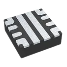
TPS259814ARPWR

TPS259814ARPWR thumbnail
Electronic Fuse Regulator High-Side 10A 10-VQFN-HR (2x2)
The TPS25981xx family of eFuses is a highly integrated circuit protection and power management solution in a small package. The devices provide multiple protection modes using very few external components and are a robust defense against overloads, short circuits, voltage surges and excessive inrush current. Output slew rate and inrush current can be adjusted using a single external capacitor. Loads are protected from input overvoltage conditions by cutting off the output if input exceeds an adjustable overvoltage threshold. The devices respond to output overload by actively limiting the current (during startup) or breaking the circuit (during steady-state). The overcurrent protection threshold as well as the transient overcurrent blanking timer are useradjustable. The current limit control pin also functions as an analog load current monitor. The devices are available in a 2-mm × 2-mm, 10- pin HotRod™ QFN package for improved thermal performance and reduced system footprint. The devices are characterized for operation over a junction temperature range of –40°C to +125°C.
• Wide operating input voltage range: 2.7 V to 16 V – 20-V absolute maximum • Integrated FET with low on-resistance: RON = 6 mΩ (typ.) • Fast overvoltage protection – Adjustable overvoltage lockout (OVLO) with 1.2-μs (typ.) response time • Overcurrent protection with load current monitor output (ILM) – Circuit-breaker response – Adjustable threshold (ILIM) 1.5 A – 11 A • ±10% accuracy for ILIM > 5 A – Adjustable transient blanking timer (ITIMER) to allow peak currents up to 2 × ILIM – Output load current monitor accuracy: ±10% (IOUT ≥ 3 A) • Fast-trip response for short-circuit protection – 640-ns (typ.) response time – Adjustable (2 × ILIM) and fixed thresholds • Active high enable input with adjustable undervoltage lockout threshold (UVLO) • Active low enable input with adjustable undervoltage lockout threshold (OVLO) • Adjustable output slew rate control (dVdt) • Option to drive external FET for reverse current blocking in disabled/OFF state • Overtemperature protection • Quick Output Discharge • Digital outputs – Power Good (PG) and fault indication (FLT) • UL 2367 recognition (pending) • IEC 62368 CB certification (pending) • Small footprint: QFN 2-mm × 2-mm, 0.45-mm pitch

Properties

TPS259814ARPWR

Texas Instruments

Integrated Circuit

IC

TO

parametric-v1

Pricing & Availability

See prices from popular manufacturers for your project.

Controls