Part Datasheet Review and Validation
Thought for 1 min 57 sec
Part review result
1) Available part information
2) Datasheet URL check
Environmental / operating conditions
Absolute maximum ratings / limiting values
Recommended PCB layout
Materials / finishes
Special features
4) Symbol and footprint cross-check
What matches
Issues / risks found
Bottom line
Table
| Field | Value |
|---|---|
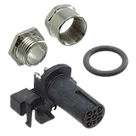
| Manufacturer | TE Connectivity |
| MPN | T4145035051-001 |
| Project description | 5 Position Circular Connector, Wire-to-Panel, Sealable, Wire & Cable, Signal, Panel Mount & Board Mount, Reverse Gender, Nickel, M12 Connector |
| TE internal description | M12 R/A F PNL STAMPED PIN A-CODE 5P SHLD |
| Connector family | M12, A-coded |
| Positions | 5 signal contacts + 1 shield connection |
| Mounting | Panel Mount & Board Mount |
| PCB termination | Through Hole - Solder |
| Orientation | Right-angle / angled |
| Shell size | 12 |
| Symbol content | 6 schematic terminals: pins 1-5 plus shield |
| Footprint content | 6 plated holes for electrical contacts and shield, plus 4 NPTH mechanical holes |
| 3D model | Present |
| Datasheet URL property | Already set: https://www.te.com/en/product-T4145035051-001.html |
- A datasheet/document URL was already set on the part, so no property update was needed.
- The official TE documents behind that product page include:
- Catalog PDF
- Product specification PDF
- Customer drawing PDF
Table
| Parameter | Value |
|---|---|
| Rated voltage | 60 V |
| Rated current | 4 A |
| Insulation resistance | 100 MΩ min. |
| Contact resistance | 10 mΩ max. initial, Δ15 mΩ max. after test |
| Voltage proof | 1000 V AC or DC for 1 minute between adjacent contacts / contacts and shield |
Table
| Parameter | Value |
|---|---|
| Operating temperature range | -40 °C to +85 °C for panel mount connectors |
| Sealing | IP67 |
| Dust sealing | IP6X |
| Seal material | Silicone |
| O-ring material | Silicone |
- No section explicitly titled Absolute Maximum Ratings was found.
- The closest limiting values present in the specification are:
- 60 V
- 4 A
- 1000 V AC/DC for 1 minute dielectric withstand
- -40 °C to +85 °C
- IP67
Table
| Pin / contact | Datasheet info |
|---|---|
| Pin 1 | Electrical contact; mating-face location top-left |
| Pin 2 | Electrical contact; mating-face location top-right |
| Pin 3 | Electrical contact; mating-face location bottom-center |
| Pin 4 | Electrical contact; mating-face location bottom-left |
| Pin 5 | Electrical contact; mating-face location bottom-right |
| Shield | Separate shield connection hole below the 5-pin pattern |
- The documents provide pin numbering and arrangement, but not application-level signal names or per-pin functional descriptions beyond contact identity.
Table
| Parameter | Value |
|---|---|
| Mounting thread | M12 |
| Hex size | SW 15 |
| Overall length | 26.0 mm |
| Front width across housing | 16.0 mm |
| Recommended panel hole | Ø12.20 ±0.10 mm |
| Supported panel thickness | 2.0 mm to 3.0 mm |
| Recommended PCB thickness | 1.6 mm |
| Recommended tightening torque | 0.6 Nm |
Table
| Feature | Value |
|---|---|
| Signal pin drill | Ø1.30 ±0.05 mm |
| Shield contact drill | Ø1.30 ±0.05 mm |
| Mechanical NPTH holes | 2x Ø2.35 ±0.05 mm, 2x Ø2.80 ±0.05 mm |
| Positional tolerance | 0.05 relative to datums X and Y |
Table
| Item | Material / finish |
|---|---|
| Contacts | Bronze, Gold flash |
| Housing | PA66, black |
| O-rings | Silicone |
| Coupling nut | Brass |
| Nut | Brass |
| Spacer | PA66 |
| Shielding | Brass |
Table
| Feature | Value |
|---|---|
| Coding | A-coded |
| Shielding | Shielded construction is indicated in drawing/spec description |
| Sealing | IP67 |
| Orientation | Right-angle |
| Gender | Receptacle / socket / reverse gender |
| Termination | Stamped pin, through-hole solder |
| Mounting style | Rear mount PCB / panel receptacle |
Table
| Check | Result |
|---|---|
| Contact count | Pass - symbol exposes 6 electrical terminals and footprint has 6 plated electrical holes |
| Signal contact drills | Pass - footprint uses 1.3 mm drills, matching drawing for pins 1-5 |
| Shield hole drill | Pass - footprint shield pad also uses 1.3 mm, matching the drawing’s shield contact hole |
| Mechanical holes | Pass - footprint includes 2x 2.35 mm NPTH and 2x 2.80 mm NPTH, matching drawing |
| Mounting style | Pass - footprint is consistent with right-angle panel/PCB receptacle geometry |
Table
| Severity | Finding | Why it matters |
|---|---|---|
| Medium | The shield terminal is named SHEILD instead of SHIELD | This is a typo risk. It may not break fabrication directly, but it can cause confusion in net naming, documentation, reviews, and downstream integration. |
| Medium | Symbol pin types are all Unspecified | For a connector part this usually will not stop manufacturing, but it weakens ERC quality and can hide connection mistakes. |
| Low | There is a document inconsistency on shielding in TE materials | The internal description and drawing clearly indicate shielding, while one catalog extraction labeled shield as No. Because the drawing includes a shield contact and shielding hardware, the part project appears to be modeled as shielded, which is the safer interpretation. |
| Low | No application-level pin functions are defined | The symbol only captures numbered contacts, not signal roles. Fine for a generic connector part, but users must assign signal meaning at design time. |
- The footprint appears mechanically consistent with the TE drawing.
- The symbol-to-footprint pin count is consistent for 5 contacts + shield.
- I do not see a footprint mismatch that would obviously cause wrong drilling, wrong pad count, or immediate assembly failure.
- The main cleanup item is the typo on SHEILD and, secondarily, assigning better connector pin electrical types.
Fix shield pin name
Run review checks
Inspect this part