Part Datasheet Review and Validation
1:57
Using Schematic Tool.
Using BOM Tool.
Fetching web page.
Using PCB Layout Tool.
Looking for "Catalog table entry for T4145035051-001 with part description, coding, positions, gender, shield, orientation, and key orderable attributes." in DDEController?Action=srchrtrv&DocNm=1-1773701-8_M8M12_CONNECTOR_SYSTEM&DocType=Catalog%20Section&DocLang=English&DocFormat=pdf&PartCntxt=T4145035051-001
Looking for "Electrical and environmental characteristics for M12 A-coded 5 position shielded panel receptacle relevant to T4145035051-001." in DDEController?Action=srchrtrv&DocNm=1-1773701-8_M8M12_CONNECTOR_SYSTEM&DocType=Catalog%20Section&DocLang=English&DocFormat=pdf&PartCntxt=T4145035051-001
Looking for "Pin numbering, pin arrangement, mating face view, and contact assignment for T4145035051-001." in DDEController?Action=srchrtrv&DocNm=T41450350X1001&DocType=Customer%20Drawing&DocLang=English&DocFormat=pdf&PartCntxt=T4145035051-001
Looking for "PCB layout dimensions including hole diameters, pad diameters, spacing, and recommended board footprint for T4145035051-001." in DDEController?Action=srchrtrv&DocNm=T41450350X1001&DocType=Customer%20Drawing&DocLang=English&DocFormat=pdf&PartCntxt=T4145035051-001
Looking for "Mechanical dimensions for body size, panel cutout, thread, mounting geometry, and overall dimensions of T4145035051-001." in DDEController?Action=srchrtrv&DocNm=T41450350X1001&DocType=Customer%20Drawing&DocLang=English&DocFormat=pdf&PartCntxt=T4145035051-001
Looking for "Notes about tolerances, materials, finish, shielding shell connection, and manufacturing requirements for T4145035051-001." in DDEController?Action=srchrtrv&DocNm=T41450350X1001&DocType=Customer%20Drawing&DocLang=English&DocFormat=pdf&PartCntxt=T4145035051-001
Looking for "Electrical characteristics for T4145035051-001 including rated voltage, current, insulation resistance, contact resistance, and temperature range." in DDEController?Action=srchrtrv&DocNm=108-106140&DocType=Specification%20Or%20Standard&DocLang=English&DocFormat=pdf&PartCntxt=T4145035051-001
Looking for "Absolute maximum ratings or limiting values for T4145035051-001." in DDEController?Action=srchrtrv&DocNm=108-106140&DocType=Specification%20Or%20Standard&DocLang=English&DocFormat=pdf&PartCntxt=T4145035051-001
Looking for "Recommended operating conditions or normal use conditions for T4145035051-001." in DDEController?Action=srchrtrv&DocNm=108-106140&DocType=Specification%20Or%20Standard&DocLang=English&DocFormat=pdf&PartCntxt=T4145035051-001
Looking for "Special features, coding, shielding, sealing, termination style, mounting style, and connector family details for T4145035051-001." in DDEController?Action=srchrtrv&DocNm=108-106140&DocType=Specification%20Or%20Standard&DocLang=English&DocFormat=pdf&PartCntxt=T4145035051-001
Investig.
Looking for "For T4145035051-001, identify which holes in the recommended PCB layout are electrical contacts versus non-plated mounting or retention holes. Include the shield hole, pin 1 through pin 5 holes, and any NPTH holes." in DDEController?Action=srchrtrv&DocNm=T41450350X1001&DocType=Customer%20Drawing&DocLang=English&DocFormat=pdf&PartCntxt=T4145035051-001
Looking for "For T4145035051-001, what is the diameter of the shield contact hole in the recommended PCB layout, and is it plated or intended as an electrical shield connection?" in DDEController?Action=srchrtrv&DocNm=T41450350X1001&DocType=Customer%20Drawing&DocLang=English&DocFormat=pdf&PartCntxt=T4145035051-001
Looking for "For T4145035051-001, list the exact mating-face pin locations or relative arrangement of pins 1, 2, 3, 4, 5 and the shield." in DDEController?Action=srchrtrv&DocNm=T41450350X1001&DocType=Customer%20Drawing&DocLang=English&DocFormat=pdf&PartCntxt=T4145035051-001
1) Available part information
| Field | Value |
|---|---|
| Manufacturer | TE Connectivity |
| MPN | T4145035051-001 |
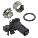
| Project description | 5 Position Circular Connector, Wire-to-Panel, Sealable, Wire & Cable, Signal, Panel Mount & Board Mount, Reverse Gender, Nickel, M12 Connector |
| TE internal description | M12 R/A F PNL STAMPED PIN A-CODE 5P SHLD |
| Connector family | M12, A-coded |
| Positions | 5 signal contacts + 1 shield connection |
| Mounting | Panel Mount & Board Mount |
| PCB termination | Through Hole - Solder |
| Orientation | Right-angle / angled |
| Shell size | 12 |
| Symbol content | 6 schematic terminals: pins 1-5 plus shield |
| Footprint content | 6 plated holes for electrical contacts and shield, plus 4 NPTH mechanical holes |
| 3D model | Present |
| Datasheet URL property | Already set: https://www.te.com/en/product-T4145035051-001.html |
- A datasheet/document URL was already set on the part, so no property update was needed.
- The official TE documents behind that product page include:
- Catalog PDF
- Product specification PDF
- Customer drawing PDF
Electrical characteristics
| Parameter | Value |
|---|---|
| Rated voltage | 60 V |
| Rated current | 4 A |
| Insulation resistance | 100 MΩ min. |
| Contact resistance | 10 mΩ max. initial, Δ15 mΩ max. after test |
| Voltage proof | 1000 V AC or DC for 1 minute between adjacent contacts / contacts and shield |
Environmental / operating conditions
| Parameter | Value |
|---|---|
| Operating temperature range | -40 °C to +85 °C for panel mount connectors |
| Sealing | IP67 |
| Dust sealing | IP6X |
| Seal material | Silicone |
| O-ring material | Silicone |
- No section explicitly titled Absolute Maximum Ratings was found.
- The closest limiting values present in the specification are:
- 60 V
- 4 A
- 1000 V AC/DC for 1 minute dielectric withstand
- -40 °C to +85 °C
- IP67
Pin descriptions
| Pin / contact | Datasheet info |
|---|---|
| Pin 1 | Electrical contact; mating-face location top-left |
| Pin 2 | Electrical contact; mating-face location top-right |
| Pin 3 | Electrical contact; mating-face location bottom-center |
| Pin 4 | Electrical contact; mating-face location bottom-left |
| Pin 5 | Electrical contact; mating-face location bottom-right |
| Shield | Separate shield connection hole below the 5-pin pattern |
- The documents provide pin numbering and arrangement, but not application-level signal names or per-pin functional descriptions beyond contact identity.
Mechanical / package dimensions
| Parameter | Value |
|---|---|
| Mounting thread | M12 |
| Hex size | SW 15 |
| Overall length | 26.0 mm |
| Front width across housing | 16.0 mm |
| Recommended panel hole | Ø12.20 ±0.10 mm |
| Supported panel thickness | 2.0 mm to 3.0 mm |
| Recommended PCB thickness | 1.6 mm |
| Recommended tightening torque | 0.6 Nm |
Recommended PCB layout
| Feature | Value |
|---|---|
| Signal pin drill | Ø1.30 ±0.05 mm |
| Shield contact drill | Ø1.30 ±0.05 mm |
| Mechanical NPTH holes | 2x Ø2.35 ±0.05 mm, 2x Ø2.80 ±0.05 mm |
| Positional tolerance | 0.05 relative to datums X and Y |
Materials / finishes
| Item | Material / finish |
|---|---|
| Contacts | Bronze, Gold flash |
| Housing | PA66, black |
| O-rings | Silicone |
| Coupling nut | Brass |
| Nut | Brass |
| Spacer | PA66 |
| Shielding | Brass |
Special features
| Feature | Value |
|---|---|
| Coding | A-coded |
| Shielding | Shielded construction is indicated in drawing/spec description |
| Sealing | IP67 |
| Orientation | Right-angle |
| Gender | Receptacle / socket / reverse gender |
| Termination | Stamped pin, through-hole solder |
| Mounting style | Rear mount PCB / panel receptacle |
What matches
| Check | Result |
|---|---|
| Contact count | Pass - symbol exposes 6 electrical terminals and footprint has 6 plated electrical holes |
| Signal contact drills | Pass - footprint uses 1.3 mm drills, matching drawing for pins 1-5 |
| Shield hole drill | Pass - footprint shield pad also uses 1.3 mm, matching the drawing’s shield contact hole |
| Mechanical holes | Pass - footprint includes 2x 2.35 mm NPTH and 2x 2.80 mm NPTH, matching drawing |
| Mounting style | Pass - footprint is consistent with right-angle panel/PCB receptacle geometry |
Issues / risks found
| Severity | Finding | Why it matters |
|---|---|---|
| Medium | The shield terminal is named SHEILD instead of SHIELD | This is a typo risk. It may not break fabrication directly, but it can cause confusion in net naming, documentation, reviews, and downstream integration. |
| Medium | Symbol pin types are all Unspecified | For a connector part this usually will not stop manufacturing, but it weakens ERC quality and can hide connection mistakes. |
| Low | There is a document inconsistency on shielding in TE materials | The internal description and drawing clearly indicate shielding, while one catalog extraction labeled shield as No. Because the drawing includes a shield contact and shielding hardware, the part project appears to be modeled as shielded, which is the safer interpretation. |
| Low | No application-level pin functions are defined | The symbol only captures numbered contacts, not signal roles. Fine for a generic connector part, but users must assign signal meaning at design time. |
- The footprint appears mechanically consistent with the TE drawing.
- The symbol-to-footprint pin count is consistent for 5 contacts + shield.
- I do not see a footprint mismatch that would obviously cause wrong drilling, wrong pad count, or immediate assembly failure.
- The main cleanup item is the typo on SHEILD and, secondarily, assigning better connector pin electrical types.
Ready.
Reviews

- Wirelessly connects nets on schematic. Used to organize schematics and separate functional blocks. To wirelessly connect net portals, give them same designator. #portaljharwinbarrozo43.0M
- Wirelessly connects power nets on schematic. Identical to the net portal, but with a power symbol. Used to organize schematics and separate functional blocks. To wirelessly connect power net portals, give them the same designator. #portal #powerjharwinbarrozo11.4M
- A generic fixed resistor for rapid developing circuit topology. Save precious design time by seamlessly add more information to this part (value, footprint, etc.) as it becomes available. Standard resistor values: 1.0Ω 10Ω 100Ω 1.0kΩ 10kΩ 100kΩ 1.0MΩ 1.1Ω 11Ω 110Ω 1.1kΩ 11kΩ 110kΩ 1.1MΩ 1.2Ω 12Ω 120Ω 1.2kΩ 12kΩ 120kΩ 1.2MΩ 1.3Ω 13Ω 130Ω 1.3kΩ 13kΩ 130kΩ 1.3MΩ 1.5Ω 15Ω 150Ω 1.5kΩ 15kΩ 150kΩ 1.5MΩ 1.6Ω 16Ω 160Ω 1.6kΩ 16kΩ 160kΩ 1.6MΩ 1.8Ω 18Ω 180Ω 1.8KΩ 18kΩ 180kΩ 1.8MΩ 2.0Ω 20Ω 200Ω 2.0kΩ 20kΩ 200kΩ 2.0MΩ 2.2Ω 22Ω 220Ω 2.2kΩ 22kΩ 220kΩ 2.2MΩ 2.4Ω 24Ω 240Ω 2.4kΩ 24kΩ 240kΩ 2.4MΩ 2.7Ω 27Ω 270Ω 2.7kΩ 27kΩ 270kΩ 2.7MΩ 3.0Ω 30Ω 300Ω 3.0KΩ 30KΩ 300KΩ 3.0MΩ 3.3Ω 33Ω 330Ω 3.3kΩ 33kΩ 330kΩ 3.3MΩ 3.6Ω 36Ω 360Ω 3.6kΩ 36kΩ 360kΩ 3.6MΩ 3.9Ω 39Ω 390Ω 3.9kΩ 39kΩ 390kΩ 3.9MΩ 4.3Ω 43Ω 430Ω 4.3kΩ 43KΩ 430KΩ 4.3MΩ 4.7Ω 47Ω 470Ω 4.7kΩ 47kΩ 470kΩ 4.7MΩ 5.1Ω 51Ω 510Ω 5.1kΩ 51kΩ 510kΩ 5.1MΩ 5.6Ω 56Ω 560Ω 5.6kΩ 56kΩ 560kΩ 5.6MΩ 6.2Ω 62Ω 620Ω 6.2kΩ 62KΩ 620KΩ 6.2MΩ 6.8Ω 68Ω 680Ω 6.8kΩ 68kΩ 680kΩ 6.8MΩ 7.5Ω 75Ω 750Ω 7.5kΩ 75kΩ 750kΩ 7.5MΩ 8.2Ω 82Ω 820Ω 8.2kΩ 82kΩ 820kΩ 8.2MΩ 9.1Ω 91Ω 910Ω 9.1kΩ 91kΩ 910kΩ 9.1MΩ #generics #CommonPartsLibraryjharwinbarrozo1.5M
- A generic fixed capacitor ideal for rapid circuit topology development. You can choose between polarized and non-polarized types, its symbol and the footprint will automatically adapt based on your selection. Supported options include standard SMD sizes for ceramic capacitors (e.g., 0402, 0603, 0805), SMD sizes for aluminum electrolytic capacitors, and through-hole footprints for polarized capacitors. Save precious design time by seamlessly add more information to this part (value, footprint, etc.) as it becomes available. Standard capacitor values: 1.0pF 10pF 100pF 1000pF 0.01uF 0.1uF 1.0uF 10uF 100uF 1000uF 10,000uF 1.1pF 11pF 110pF 1100pF 1.2pF 12pF 120pF 1200pF 1.3pF 13pF 130pF 1300pF 1.5pF 15pF 150pF 1500pF 0.015uF 0.15uF 1.5uF 15uF 150uF 1500uF 1.6pF 16pF 160pF 1600pF 1.8pF 18pF 180pF 1800pF 2.0pF 20pF 200pF 2000pF 2.2pF 22pF 20pF 2200pF 0.022uF 0.22uF 2.2uF 22uF 220uF 2200uF 2.4pF 24pF 240pF 2400pF 2.7pF 27pF 270pF 2700pF 3.0pF 30pF 300pF 3000pF 3.3pF 33pF 330pF 3300pF 0.033uF 0.33uF 3.3uF 33uF 330uF 3300uF 3.6pF 36pF 360pF 3600pF 3.9pF 39pF 390pF 3900pF 4.3pF 43pF 430pF 4300pF 4.7pF 47pF 470pF 4700pF 0.047uF 0.47uF 4.7uF 47uF 470uF 4700uF 5.1pF 51pF 510pF 5100pF 5.6pF 56pF 560pF 5600pF 6.2pF 62pF 620pF 6200pF 6.8pF 68pF 680pF 6800pF 0.068uF 0.68uF 6.8uF 68uF 680uF 6800uF 7.5pF 75pF 750pF 7500pF 8.2pF 82pF 820pF 8200pF 9.1pF 91pF 910pF 9100pF #generics #CommonPartsLibraryjharwinbarrozo1.5M
- A generic fixed inductor for rapid developing circuit topology. *You can now change the footprint and 3D model at the top level anytime you want. This is the power of #genericsjharwinbarrozo15.5k
- An electrical connector acting as reusable interface to a conductor and creating a point where external circuits can be connected.Terminal
- 47 kOhms ±5% 0.125W, 1/8W Chip Resistor 0805 (2012 Metric) Automotive AEC-Q200 Thick Film #forLedBlinkjharwinbarrozo1.2M
- 10uF Capacitor Aluminum Polymer 20% 16V SMD 5x5.3mm #forLedBlink #commonpartslibrary #capacitor #aluminumpolymer #radialcanjharwinbarrozo1.2M
- Yellow 595nm LED Indication - Discrete 1.7V 1206 (3216 Metric) #forLedBlinkjharwinbarrozo1.1M


Pricing & Availability
See prices from popular manufacturers for your project.
Assets

T4145035051-001-thumb.png
T4145035051-001-thumbThumbnail
T4145035051-001
T4145035051-001 Symbol.svgDefaultT4145035051-001
T4145035051-001.stp3D ModelT4145035051-001
T4145035051001.kicad_modFootprintControls
Welcome 👋
Flux accelerates your PCB design with AI.
Create your account to start using this component and bring your ideas to life.