Pin Function Grouping
Worked for 2 mins
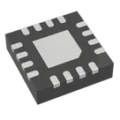
Yes. Using the datasheet’s pin table, here is a deduplicated functional grouping for the bq24075 variant. I’ve put each pin in one group only, so pins are not repeated across categories. The pin names and functions come directly from the datasheet pin table
Pin Groups
Table
| Group | Pins | Why they belong together |
|---|---|---|
| Power Input | IN (13) | Main external input supply pin |
| Battery / Power Path | BAT (2, 3), OUT (10, 11) | Battery node and system output / power-path pins |
| Ground | VSS (8), Thermal Pad / EP | Ground return; datasheet says the exposed pad is internally connected to VSS |
| Charge / Input Programming | ISET (16), ILIM (12), TMR (14) | Pins used to program fast-charge current, input current limit, and safety timer behavior |
| Control | CE (4), EN1 (6), EN2 (5), SYSOFF (15) | Charger enable, USB/input-current mode selection, and system enable control |
| Status Outputs | PGOOD (7), CHG (9) | Open-drain status indication outputs for input-valid and charging state |
| Monitoring / Sense | TS (1) | Battery temperature monitoring input via NTC divider |
Pin Group names
A clean way to assign them would be:
Table
| Pin | Suggested Pin Group |
|---|---|
| TS | TS |
| BAT, BAT | BAT |
| CE | Control |
| EN2, EN1 | Control |
| PGOOD, CHG | Status |
| VSS, EP | Ground |
| OUT, OUT | OUT |
| ILIM, ISET, TMR | Charge_Program |
| IN | Power |
| SYSOFF | Control |
- For the bq24075, pin 15 is
SYSOFF. The datasheet showsTDon pin 15 only for the bq24072, not for the bq24075 - The thermal pad should be grouped with ground, not as a separate power pin, because the datasheet states it is internally connected to VSS
If you want, I can turn this next into:
- a Section assignment,
- Pin Group assignment,
- and Pin Type assignment for every terminal in your part project.
Assign pin groups
Fix control naming
Check pad grouping