Part Information Review and Verification

Part review summary
I reviewed the current part project against the datasheet URL already on the project, so I did not change the Datasheet property. The review flow I followed is consistent with the part-project sync guidance: verify the Datasheet URL first, then compare project properties and terminals against the datasheet, and only update missing/incorrect fields when the datasheet is authoritative
What is currently in the project

Table


FieldCurrent valueReview result
Manufacturer Part NumberBMI-S-203-FNeeds attention
Manufacturer NameLairdLikely OK
Designator PrefixUUnusual for this part type
Datasheet URLSetPresent, so no web search/update was needed
DescriptionEMI Gaskets, Sheets, Absorbers & Shielding SBS,FRAM,TnRMismatch / low quality
Schematic symbol20 terminals numbered 1 to 20Needs verification
Footprint20 pads numbered 1 to 20Needs verification
Pin Type metadataAll terminals = UnspecifiedIncomplete
Datasheet facts I could confirm
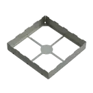
From the linked Laird PDF, the part is described as a Standard Surface Mount Shields-Two-Piece family item, with these retrieved specs:

Table


Datasheet itemValue
DescriptionStandard Surface Mount Shields-Two-Piece
Maximum overall dimension26.21 mm x 26.21 mm
Maximum overall height5.08 mm
Surface area666.16 mm²
Material thickness0.20 mm
Material0.20 mm CRS Tin
Weight1.0 g
PackagingEIA-481
Carrier tape width44 mm
Carrier tape pitch32 mm
Reel diameter330 mm
Parts per reel300
Coplanarity** 99%**
The same retrieved datasheet content also explicitly does not include a pin table, pin names, terminal descriptions, footprint recommendation, or recommended land pattern. The only pin-related text retrieved is a list of compatible device/package categories like 32/44/52 pin PLCC, 121/169 BGA, 48/100 VQFP, and 44/48/64/80 QFP; it does not provide a terminal map for this shield itself
Key mismatches and issues 1. Description mismatch
Your current description says:
  • EMI Gaskets, Sheets, Absorbers & Shielding SBS,FRAM,TnR
But the linked datasheet content identifies the item as:
  • Standard Surface Mount Shields-Two-Piece
So the description is currently too generic and does not match the datasheet wording well. The sync guidance specifically recommends a crisp functional description based on the datasheet rather than a vague category string
2. MPN looks potentially inconsistent
The project MPN is BMI-S-203-F, but the datasheet content I could retrieve is branded around BMIS-203 / Item # BMIS-203. That suggests one of these is true:
  • BMI-S-203-F is a valid ordering suffix/variant of the BMIS-203 family, or
  • the project MPN has a typo / formatting mismatch.
I can’t resolve that conclusively from the current PDF extract alone, so I’m flagging it as a likely metadata mismatch.
3. Symbol cannot be verified from the datasheet
The project symbol currently has 20 numbered terminals, all with Pin Type = Unspecified. For a part-project audit, the rule is to match terminal count and pin definitions exactly to the datasheet and never guess pin assignments
Here, that verification is not possible because the retrieved datasheet content has:
  • no pin table
  • no pin names
  • no terminal descriptions
  • no explicit terminal count for the shield itself
So I cannot confirm whether the 20-terminal symbol is correct or incorrect from the datasheet.
4. Footprint cannot be verified from the datasheet
The PCB model currently has 20 pads numbered 1 to 20, matching the schematic terminal count. However, the retrieved datasheet content includes only overall mechanical dimensions and tape-and-reel data, with no recommended land pattern or footprint drawing
That means I cannot verify:
  • pad count
  • pad geometry
  • pad spacing
  • courtyard / outline accuracy
  • whether the 20-pad footprint matches the official recommended layout
5. Terminal metadata is incomplete
All 20 terminals are present only as numbered terminals with:
  • Pin Number set
  • Pin Type = Unspecified
  • no pin descriptions
The sync guidance says those fields should be filled from the datasheet when available, but should not be guessed when the datasheet lacks authoritative pin info
For this part, since the datasheet extract does not provide terminal definitions, leaving them unspecified is safer than inventing them.
Overall assessment Confirmed OK

Table


ItemStatus
Datasheet URL presentOK
Manufacturer name broadly matches Laird/Laird TechnologiesOK
Basic mechanical specs in project context can be derived from datasheet if neededOK
Flagged

Table


ItemStatus
Project descriptionMismatch
MPN BMI-S-203-F vs datasheet BMIS-203 family namingPotential mismatch
Symbol pinoutUnverifiable from current datasheet
Footprint pad patternUnverifiable from current datasheet
Pin descriptions / pin typesMissing, but datasheet does not support filling them confidently
Designator prefix UProbably not ideal for a shield/mechanical part
Recommended next steps
  1. Check whether BMI-S-203-F is the exact ordering code for the BMIS-203 family.
  2. Update the project description to something like:
    Two-piece SMT EMI shield frame and cover, 26.21 mm x 26.21 mm max, 5.08 mm height, 0.20 mm CRS tin
  3. Do not auto-edit pin descriptions or pin types unless you have a more detailed mechanical drawing or footprint drawing from Laird.
  4. Find a mechanical drawing / recommended land pattern for the exact suffix if you want a real symbol/footprint verification. The current linked PDF is not enough to validate the 20-pad implementation.
If you want, I can do the next pass and clean up the project metadata/description now, then separately search for a more exact mechanical drawing or official land-pattern document for BMI-S-203-F.
Fix flagged mismatches
Review power parts first
Check footprints too
Save review notes


  • Generic Inductor
    A generic fixed inductor suitable for rapid circuit topology development. The footprint automatically adapts based on the selected package, supporting standard SMD sizes (e.g., 0402, 0603, 0805) as well as well-known inductor packages such as SDR1806, PA4320, SRN6028, and SRR1260. Standard inductor values: 1.0 nH, 10 nH, 100 nH, 1.0 µH, 10 µH, 100 µH, 1.0 mH 1.2 nH, 12 nH, 120 nH, 1.2 µH, 12 µH, 120 µH, 1.2 mH 1.5 nH, 15 nH, 150 nH, 1.5 µH, 15 µH, 150 µH, 1.5 mH 1.8 nH, 18 nH, 180 nH, 1.8 µH, 18 µH, 180 µH, 1.8 mH 2.2 nH, 22 nH, 220 nH, 2.2 µH, 22 µH, 220 µH, 2.2 mH 2.7 nH, 27 nH, 270 nH, 2.7 µH, 27 µH, 270 µH, 2.7 mH 3.3 nH, 33 nH, 330 nH, 3.3 µH, 33 µH, 330 µH, 3.3 mH 3.9 nH, 39 nH, 390 nH, 3.9 µH, 39 µH, 390 µH, 3.9 mH 4.7 nH, 47 nH, 470 nH, 4.7 µH, 47 µH, 470 µH, 4.7 mH 5.6 nH, 56 nH, 560 nH, 5.6 µH, 56 µH, 560 µH, 5.6 mH 6.8 nH, 68 nH, 680 nH, 6.8 µH, 68 µH, 680 µH, 6.8 mH 8.2 nH, 82 nH, 820 nH, 8.2 µH, 82 µH, 820 µH, 8.2 mH #generics #CommonPartsLibrary
  • Generic Capacitor
    A generic fixed capacitor ideal for rapid circuit topology development. You can choose between polarized and non-polarized types, its symbol and the footprint will automatically adapt based on your selection. Supported options include standard SMD sizes for ceramic capacitors (e.g., 0402, 0603, 0805), SMD sizes for aluminum electrolytic capacitors, and through-hole footprints for polarized capacitors. Save precious design time by seamlessly add more information to this part (value, footprint, etc.) as it becomes available. Standard capacitor values: 1.0pF, 10pF, 100pF, 1000pF, 0.01uF, 0.1uF, 1.0uF, 10uF, 100uF, 1000uF, 10000uF 1.1pF, 11pF, 110pF, 1100pF 1.2pF, 12pF, 120pF, 1200pF 1.3pF, 13pF, 130pF, 1300pF 1.5pF, 15pF, 150pF, 1500pF, 0.015uF, 0.15uF, 1.5uF, 15uF, 150uF, 1500uF 1.6pF, 16pF, 160pF, 1600pF 1.8pF, 18pF, 180pF, 1800pF 2.0pF, 20pF, 200pF, 2000pF 2.2pF, 22pF, 220pF, 2200pF, 0.022uF, 0.22uF, 2.2uF, 22uF, 220uF, 2200uF 2.4pF, 24pF, 240pF, 2400pF 2.7pF, 27pF, 270pF, 2700pF 3.0pF, 30pF, 300pF, 3000pF 3.3pF, 33pF, 330pF, 3300pF, 0.033uF, 0.33uF, 3.3uF, 33uF, 330uF, 3300uF 3.6pF, 36pF, 360pF, 3600pF 3.9pF, 39pF, 390pF, 3900pF 4.3pF, 43pF, 430pF, 4300pF 4.7pF, 47pF, 470pF, 4700pF, 0.047uF, 0.47uF, 4.7uF, 47uF, 470uF, 4700uF 5.1pF, 51pF, 510pF, 5100pF 5.6pF, 56pF, 560pF, 5600pF 6.2pF, 62pF, 620pF, 6200pF 6.8pF, 68pF, 680pF, 6800pF, 0.068uF, 0.68uF, 6.8uF, 68uF, 680uF, 6800uF 7.5pF, 75pF, 750pF, 7500pF 8.2pF, 82pF, 820pF, 8200pF 9.1pF, 91pF, 910pF, 9100pF #generics #CommonPartsLibrary
  • Generic Resistor
    A generic fixed resistor ideal for rapid circuit topology development. Its footprint automatically adapts based on the selected package case code—supporting 0402, 0603, 0805, 1203, and many other standard SMD packages, as well as axial horizontal and vertical configurations. Save precious design time by seamlessly add more information to this part (value, footprint, etc.) as it becomes available. Standard resistor values: 1.0 ohm, 10 ohm, 100 ohm, 1.0k ohm, 10k ohm, 100k ohm, 1.0M ohm 1.1 ohm, 11 ohm, 110 ohm, 1.1k ohm, 11k ohm, 110k ohm, 1.1M ohm 1.2 ohm, 12 ohm, 120 ohm, 1.2k ohm, 12k ohm, 120k ohm, 1.2M ohm 1.3 ohm, 13 ohm, 130 ohm, 1.3k ohm, 13k ohm, 130k ohm, 1.3M ohm 1.5 ohm, 15 ohm, 150 ohm, 1.5k ohm, 15k ohm, 150k ohm, 1.5M ohm 1.6 ohm, 16 ohm, 160 ohm, 1.6k ohm, 16k ohm, 160k ohm, 1.6M ohm 1.8 ohm, 18 ohm, 180 ohm, 1.8K ohm, 18k ohm, 180k ohm, 1.8M ohm 2.0 ohm, 20 ohm, 200 ohm, 2.0k ohm, 20k ohm, 200k ohm, 2.0M ohm 2.2 ohm, 22 ohm, 220 ohm, 2.2k ohm, 22k ohm, 220k ohm, 2.2M ohm 2.4 ohm, 24 ohm, 240 ohm, 2.4k ohm, 24k ohm, 240k ohm, 2.4M ohm 2.7 ohm, 27 ohm, 270 ohm, 2.7k ohm, 27k ohm, 270k ohm, 2.7M ohm 3.0 ohm, 30 ohm, 300 ohm, 3.0K ohm, 30K ohm, 300K ohm, 3.0M ohm 3.3 ohm, 33 ohm, 330 ohm, 3.3k ohm, 33k ohm, 330k ohm, 3.3M ohm 3.6 ohm, 36 ohm, 360 ohm, 3.6k ohm, 36k ohm, 360k ohm, 3.6M ohm 3.9 ohm, 39 ohm, 390 ohm, 3.9k ohm, 39k ohm, 390k ohm, 3.9M ohm 4.3 ohm, 43 ohm, 430 ohm, 4.3k ohm, 43K ohm, 430K ohm, 4.3M ohm 4.7 ohm, 47 ohm, 470 ohm, 4.7k ohm, 47k ohm, 470k ohm, 4.7M ohm 5.1 ohm, 51 ohm, 510 ohm, 5.1k ohm, 51k ohm, 510k ohm, 5.1M ohm 5.6 ohm, 56 ohm, 560 ohm, 5.6k ohm, 56k ohm, 560k ohm, 5.6M ohm 6.2 ohm, 62 ohm, 620 ohm, 6.2k ohm, 62K ohm, 620K ohm, 6.2M ohm 6.8 ohm, 68 ohm, 680 ohm, 6.8k ohm, 68k ohm, 680k ohm, 6.8M ohm 7.5 ohm, 75 ohm, 750 ohm, 7.5k ohm, 75k ohm, 750k ohm, 7.5M ohm 8.2 ohm, 82 ohm, 820 ohm, 8.2k ohm, 82k ohm, 820k ohm, 8.2M ohm 9.1 ohm, 91 ohm, 910 ohm, 9.1k ohm, 91k ohm, 910k ohm, 9.1M ohm #generics #CommonPartsLibrary
  • Ground
    A common return path for electric current. Commonly known as ground.
  • Terminal
    Terminal
    An electrical connector acting as reusable interface to a conductor and creating a point where external circuits can be connected.
  • Net Portal
    Wirelessly connects nets on schematic. Used to organize schematics and separate functional blocks. To wirelessly connect net portals, give them same designator. #portal
  • RMCF0805JT47K0
    General Purpose Thick Film Standard Power and High-Power Chip Resistor 47 kOhms ±5% 0.125W, 1/8W Chip Resistor 0805 (2012 Metric) Automotive AEC-Q200 Thick Film Features: - RMCF – standard power ratings - RMCP – high power ratings - Nickel barrier terminations standard - Power derating from 100% at 70ºC to zero at +155ºC - RoHS compliant, REACH compliant, and halogen free - AEC-Q200 compliant
  • 875105359001
    10 µF 16 V Aluminum - Polymer Capacitors Radial, Can - SMD 30mOhm 2000 Hrs @ 105°C #commonpartslibrary #capacitor #aluminumpolymer #radialcan
  • CTL1206FYW1T
    Yellow 595nm LED Indication - Discrete 1.7V 1206 (3216 Metric)
  • 1070TR
    Battery Holder (Open) Coin, 20.0mm 1 Cell SMD (SMT) Tab bate or batt #forLedBlink

BMI-S-203-F

BMI-S-203-F thumbnail
RF Shield Frame 1.032" (26.21mm) X 1.032" (26.21mm) Surface Mount The BMI-S-203-F is a surface-mount EMI shield frame (part of a board-level shielding system) manufactured by Laird (now part of DuPont Performance Materials). It is used to enclose and isolate sensitive components on a PCB, helping prevent signal interference and improving electromagnetic compatibility (EMC). It typically comes as a one-piece or frame-style shield that is soldered directly onto the PCB, forming a metallic “cage” over critical circuits. Key Characteristics Product Type: Board-level EMI/RFI shielding enclosure Shield Style: Surface-mount frame (soldered to PCB) Dimensions: ~26.21 mm × 26.21 mm × 5.08 mm Construction Material: Typically cold rolled steel or similar conductive metal Finish: Tin-plated for good solderability Mounting: SMT (surface mount technology) Configuration: Designed for use with cover lids or as part of a two-piece shielding system Function Blocks unwanted electromagnetic interference (EMI) Prevents RF noise from affecting nearby sensitive circuits Improves signal integrity in high-speed or RF designs Helps meet EMC regulatory requirements Typical Applications RF modules and wireless circuits IoT devices Smartphones and compact electronics Communication systems High-speed digital and mixed-signal PCBs #RF-shield #SMT 2 Piece

Properties

BMI-S-203-F

Laird

RF Shield

U

Pricing & Availability

See prices from popular manufacturers for your project.

Controls