Part Review and Datasheet Analysis
1:01
Evalu.
Using Schematic Tool.
Using BOM Tool.
Using PCB Layout Tool.
Looking for "part description, series name, product overview, number of circuits, pitch, mounting style, orientation, and package/connector family" in 70555-0073.pdf
Looking for "electrical characteristics" in 70555-0073.pdf
Looking for "absolute maximum ratings" in 70555-0073.pdf
Looking for "recommended operating conditions" in 70555-0073.pdf
Looking for "pin descriptions or contact numbering" in 70555-0073.pdf
Looking for "package dimensions and recommended PCB layout" in 70555-0073.pdf
Looking for "special features, materials, plating, current rating, voltage rating, insulation resistance, contact resistance, dielectric withstanding voltage, temperature range" in 70555-0073.pdf
Part project review
| Item | Result |
|---|---|
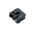
| MPN | 70555-0073 |
| Manufacturer | Molex |
| Description in project | Headers & Wire Housings R/A HDR TRI-PEG 4P low profile |
| Datasheet URL in project | Already present |
| Datasheet action needed | No - step 2 was skipped because a datasheet URL is already set |
| Schematic symbol | 4-position connector symbol with pins numbered 1-4 |
| PCB footprint present | Yes |
| 3D model present | Yes |
Datasheet summary
| Category | Extracted data |
|---|---|
| Product family | SL Modular Connectors, series 70555 |
| Full description | 2.54 mm pitch, single row, right angle, shrouded, press-fit plastic peg, 4 circuits, selective gold plating on mating area, tin plating on PC tails |
| Mounting / termination | Through hole |
| Orientation | Right angle |
| Pitch | 2.54 mm |
| Number of circuits | 4 |
| Recommended PCB thickness | 1.60 mm |
| PC tail length | 3.30 mm |
| Current rating | 3.0 A per contact |
| Voltage rating | 250 V max |
| Operating temperature | -40 C to +105 C |
| Durability | 50 mating cycles max |
| Process capability | Lead-free wave solder |
| Max process temperature | 260 C |
| Max cycles at max process temperature | 3 |
| Flammability | 94V-0 |
| Contact materials | Brass, Phosphor Bronze |
| Housing material | High temperature thermoplastic |
| Mating plating | Gold, minimum 0.762 um |
| Termination plating | Tin, minimum 1.905 um |
Datasheet gaps
| Missing from available PDF | Impact |
|---|---|
| Absolute maximum ratings table | No formal abs-max table to extract |
| Pin function descriptions | Connector is positional only; no per-pin electrical functions listed |
| Contact resistance | Could not verify from this PDF |
| Insulation resistance | Could not verify from this PDF |
| Dielectric withstanding voltage | Could not verify from this PDF |
| Detailed mechanical drawing / recommended drill map | Limits full footprint verification |
Symbol review
| Check | Result | Risk |
|---|---|---|
| Pin count | Pass - symbol has 4 positions | Low |
| Pin numbering | Pass - numbered 1-4 | Low |
| Connector type representation | Mostly pass - simple numbered connector symbol is appropriate | Low |
| Pin metadata | Concern - pins appear as undefined / unspecified in symbol data | Medium for library quality, low for fabrication |
Footprint review
| Check | Result | Risk |
|---|---|---|
| Pad count | Pass - footprint has 4 pads | Low |
| Pad numbering | Pass - pads numbered 1-4 | Low |
| Pitch consistency | Pass - pads spaced at 2.54 mm | Low |
| Mount style | Pass - through-hole pads match datasheet | Low |
| Pin 1 marking | Pass - pad 1 is rectangular | Low |
| Mechanical style | Likely pass - footprint filename/body indicate right-angle shrouded 1x4 connector | Low to medium |
| Drill / hole size | Unverified - footprint uses 1.10 mm drill, but the PDF available does not provide hole spec | Medium |
| Board outline/body size | Partially verified only - footprint asset implies body dimensions, but the PDF lacks full dimensioned drawing | Medium |
| Plastic peg / locator hole support | Unverified - datasheet says PCB locator/retention exists, but I could not confirm whether the footprint includes the required non-electrical locator hole(s) from the available inspection output | High |
Manufacturing-risk findings
| Finding | Severity | Why it matters |
|---|---|---|
| Locator / retention peg support is not confirmed | High | If the connector requires a plastic peg hole and the footprint lacks it, assembly may fail or the part may not seat correctly |
| Drill diameter cannot be validated from the available datasheet PDF | Medium | Incorrect drill size can cause insertion problems or weak solder joints |
| Symbol pin definitions are unspecified | Low to Medium | Can lead to poor library quality or ERC ambiguity, though not usually a fabrication failure for a passive connector |
| No detailed Molex mechanical drawing in the available PDF | Medium | Prevents full verification of footprint geometry, courtyard, and hole pattern |
Bottom line
| Conclusion | Result |
|---|---|
| Basic part identity matches project | Yes |
| Pin count / numbering alignment looks correct | Yes |
| Footprint appears directionally correct for a 1x4, 2.54 mm, right-angle, through-hole connector | Yes |
| Fully verified for manufacturing | No - blocked by missing detailed dimensional drawing in the available datasheet PDF |
Recommended next fix
| Priority | Recommendation |
|---|---|
| 1 | Get the full Molex sales drawing SDA-70555-** or a dimensioned mechanical drawing** for 70555-0073 |
| 2 | Confirm the footprint includes any required locator / retention peg hole(s) |
| 3 | Confirm the plated hole drill against the Molex recommended PCB pattern |
| 4 | Clean up symbol metadata so each connector pin is explicitly defined rather than left unspecified |
Ready.
Reviews

- Wirelessly connects nets on schematic. Used to organize schematics and separate functional blocks. To wirelessly connect net portals, give them same designator. #portaljharwinbarrozo43.0M
- Wirelessly connects power nets on schematic. Identical to the net portal, but with a power symbol. Used to organize schematics and separate functional blocks. To wirelessly connect power net portals, give them the same designator. #portal #powerjharwinbarrozo11.4M
- A generic fixed resistor for rapid developing circuit topology. Save precious design time by seamlessly add more information to this part (value, footprint, etc.) as it becomes available. Standard resistor values: 1.0Ω 10Ω 100Ω 1.0kΩ 10kΩ 100kΩ 1.0MΩ 1.1Ω 11Ω 110Ω 1.1kΩ 11kΩ 110kΩ 1.1MΩ 1.2Ω 12Ω 120Ω 1.2kΩ 12kΩ 120kΩ 1.2MΩ 1.3Ω 13Ω 130Ω 1.3kΩ 13kΩ 130kΩ 1.3MΩ 1.5Ω 15Ω 150Ω 1.5kΩ 15kΩ 150kΩ 1.5MΩ 1.6Ω 16Ω 160Ω 1.6kΩ 16kΩ 160kΩ 1.6MΩ 1.8Ω 18Ω 180Ω 1.8KΩ 18kΩ 180kΩ 1.8MΩ 2.0Ω 20Ω 200Ω 2.0kΩ 20kΩ 200kΩ 2.0MΩ 2.2Ω 22Ω 220Ω 2.2kΩ 22kΩ 220kΩ 2.2MΩ 2.4Ω 24Ω 240Ω 2.4kΩ 24kΩ 240kΩ 2.4MΩ 2.7Ω 27Ω 270Ω 2.7kΩ 27kΩ 270kΩ 2.7MΩ 3.0Ω 30Ω 300Ω 3.0KΩ 30KΩ 300KΩ 3.0MΩ 3.3Ω 33Ω 330Ω 3.3kΩ 33kΩ 330kΩ 3.3MΩ 3.6Ω 36Ω 360Ω 3.6kΩ 36kΩ 360kΩ 3.6MΩ 3.9Ω 39Ω 390Ω 3.9kΩ 39kΩ 390kΩ 3.9MΩ 4.3Ω 43Ω 430Ω 4.3kΩ 43KΩ 430KΩ 4.3MΩ 4.7Ω 47Ω 470Ω 4.7kΩ 47kΩ 470kΩ 4.7MΩ 5.1Ω 51Ω 510Ω 5.1kΩ 51kΩ 510kΩ 5.1MΩ 5.6Ω 56Ω 560Ω 5.6kΩ 56kΩ 560kΩ 5.6MΩ 6.2Ω 62Ω 620Ω 6.2kΩ 62KΩ 620KΩ 6.2MΩ 6.8Ω 68Ω 680Ω 6.8kΩ 68kΩ 680kΩ 6.8MΩ 7.5Ω 75Ω 750Ω 7.5kΩ 75kΩ 750kΩ 7.5MΩ 8.2Ω 82Ω 820Ω 8.2kΩ 82kΩ 820kΩ 8.2MΩ 9.1Ω 91Ω 910Ω 9.1kΩ 91kΩ 910kΩ 9.1MΩ #generics #CommonPartsLibraryjharwinbarrozo1.5M
- A generic fixed capacitor ideal for rapid circuit topology development. You can choose between polarized and non-polarized types, its symbol and the footprint will automatically adapt based on your selection. Supported options include standard SMD sizes for ceramic capacitors (e.g., 0402, 0603, 0805), SMD sizes for aluminum electrolytic capacitors, and through-hole footprints for polarized capacitors. Save precious design time by seamlessly add more information to this part (value, footprint, etc.) as it becomes available. Standard capacitor values: 1.0pF 10pF 100pF 1000pF 0.01uF 0.1uF 1.0uF 10uF 100uF 1000uF 10,000uF 1.1pF 11pF 110pF 1100pF 1.2pF 12pF 120pF 1200pF 1.3pF 13pF 130pF 1300pF 1.5pF 15pF 150pF 1500pF 0.015uF 0.15uF 1.5uF 15uF 150uF 1500uF 1.6pF 16pF 160pF 1600pF 1.8pF 18pF 180pF 1800pF 2.0pF 20pF 200pF 2000pF 2.2pF 22pF 20pF 2200pF 0.022uF 0.22uF 2.2uF 22uF 220uF 2200uF 2.4pF 24pF 240pF 2400pF 2.7pF 27pF 270pF 2700pF 3.0pF 30pF 300pF 3000pF 3.3pF 33pF 330pF 3300pF 0.033uF 0.33uF 3.3uF 33uF 330uF 3300uF 3.6pF 36pF 360pF 3600pF 3.9pF 39pF 390pF 3900pF 4.3pF 43pF 430pF 4300pF 4.7pF 47pF 470pF 4700pF 0.047uF 0.47uF 4.7uF 47uF 470uF 4700uF 5.1pF 51pF 510pF 5100pF 5.6pF 56pF 560pF 5600pF 6.2pF 62pF 620pF 6200pF 6.8pF 68pF 680pF 6800pF 0.068uF 0.68uF 6.8uF 68uF 680uF 6800uF 7.5pF 75pF 750pF 7500pF 8.2pF 82pF 820pF 8200pF 9.1pF 91pF 910pF 9100pF #generics #CommonPartsLibraryjharwinbarrozo1.5M
- A generic fixed inductor for rapid developing circuit topology. *You can now change the footprint and 3D model at the top level anytime you want. This is the power of #genericsjharwinbarrozo15.6k
- An electrical connector acting as reusable interface to a conductor and creating a point where external circuits can be connected.Terminal
- 47 kOhms ±5% 0.125W, 1/8W Chip Resistor 0805 (2012 Metric) Automotive AEC-Q200 Thick Film #forLedBlinkjharwinbarrozo1.2M
- 10uF Capacitor Aluminum Polymer 20% 16V SMD 5x5.3mm #forLedBlink #commonpartslibrary #capacitor #aluminumpolymer #radialcanjharwinbarrozo1.2M
- Yellow 595nm LED Indication - Discrete 1.7V 1206 (3216 Metric) #forLedBlinkjharwinbarrozo1.1M


Pricing & Availability
See prices from popular manufacturers for your project.
Assets
70555-0073
SHDRRA4W64P0X254_1X4_1271X1359X712P.kicad_modFootprint70555-0073
70555-0073.stp3D Model
70555-0073
70555-0073 Symbol.svgDefault
0705550073-thumb.png
0705550073-thumbThumbnailControls
Welcome 👋
Flux accelerates your PCB design with AI.
Create your account to start using this component and bring your ideas to life.