Part Datasheet Review and Cross-Check
0:54
Determining action steps.
Clarifying the next steps.
Gathering project details.
Checking if I can make the changes for you.
Using BOM Tool.
Using Schematic Tool.
Using PCB Layout Tool.
Looking for "Part description, product family, package/style, pin count, and special features." in 687130183722.pdf
Looking for "Absolute Maximum Ratings." in 687130183722.pdf
Looking for "Recommended Operating Conditions." in 687130183722.pdf
Looking for "Electrical Characteristics." in 687130183722.pdf
Looking for "Pin assignment and pin descriptions for all contacts and mounting pads." in 687130183722.pdf
Looking for "Package information and mechanical dimensions including pitch, overall size, height, and recommended PCB land pattern." in 687130183722.pdf
Project metadata
| Field | Value |
|---|---|
| Manufacturer | Würth |
| MPN | 687130183722 |
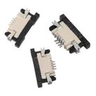
| Description | WR-FPC 0.50 mm SMT Horizontal Bottom Contact Low Profile |
| Mount | Surface Mount |
| Designator prefix | J |
| Datasheet | Datasheet |
Symbol / footprint inventory
| Item | Observed |
|---|---|
| Signal contacts in symbol | 30 |
| Mechanical pads in symbol | 2 (MP1, MP2) |
| Total symbol terminals | 32 |
| Footprint signal pads | 30 |
| Footprint mechanical pads | 2 (MP1, MP2) |
| 3D model asset | Present (687130183722.stp) |
| Footprint asset | Present (687130183722.kicad_mod) |
General
| Parameter | Value |
|---|---|
| Product family | WR-FPC Zero Insertion Force Connectors - 0.50 mm |
| Style | SMT, horizontal, bottom contact, low profile, ZIF |
| Pin count | 30 |
| Pitch | 0.50 mm |
| Packaging | Tape and reel |
| Lifecycle | Production active |
| Operating temperature | -25 °C to +85 °C |
Electrical characteristics
| Parameter | Value |
|---|---|
| Rated current | 0.4 A |
| Working voltage | 50 V AC |
| Withstanding voltage | 250 V AC for 1 min |
| Contact resistance | 30 mΩ max |
| Insulation resistance | 100 MΩ min |
Absolute maximum ratings
| Result | Notes |
|---|---|
| No explicit “Absolute Maximum Ratings” table found | The retrieved datasheet content exposes electrical/operating data, but not a separate absolute max section. For this connector, the practical limits appear to be the published rated current, working voltage, and dielectric withstand figures above. |
Recommended operating conditions
| Parameter | Value |
|---|---|
| Operating temperature | -25 °C to +85 °C |
Pin descriptions
| Result | Notes |
|---|---|
| No per-pin functional description table found | The datasheet identifies a 30-pin connector and shows the mating/contact geometry and land pattern orientation, but does not assign signal names or unique electrical functions to pins 1-30. |
| Mechanical pads | 2 solder tabs / mounting pads are shown |
Mechanical / package dimensions
| Parameter | Value |
|---|---|
| Overall length | 20.7 mm |
| Max height | 2.0 mm max |
| Mounting style | Horizontal SMT |
| Contact style | Bottom contact |
| Orientation marker | “1 End” indicated in drawing |
What matches
| Check | Result | Notes |
|---|---|---|
| Pin count | Pass | Symbol has 30 signal contacts; datasheet says 30 pins |
| Mechanical pads | Pass | Symbol and footprint both include 2 mounting pads |
| Pitch | Pass | Footprint pads are placed at 0.50 mm spacing, consistent with datasheet |
| Mount/style | Pass | Footprint is SMT and horizontal, matching datasheet |
| Bottom-contact type | Likely pass | Part metadata matches the datasheet family and style |
Risks / mismatches to flag
| Issue | Severity | Why it matters |
|---|---|---|
| No explicit per-pin datasheet table | Low | For this connector family, all signal pins are usually equivalent, so this is not necessarily wrong, but it means numbering must be validated from the mechanical drawing rather than a pin table |
| Orientation / pin-1 verification not yet proven from imported geometry text alone | High | The footprint includes a pin-1 silkscreen marker and the datasheet mentions “1 End”, but I cannot prove from the extracted text alone that the imported pad numbering direction exactly matches the Würth drawing. A reversed numbering scheme would cause cable miswiring or total board failure |
| Recommended land pattern not explicitly retrieved as dimensioned table | Medium | The footprint geometry looks internally consistent, but without a full dimensioned land-pattern extraction from the PDF, pad width, toe/heel length, and mounting-tab geometry are not fully confirmed against Würth’s recommendation |
| Current rating discrepancy in retrieved sources | Medium | One datasheet extraction returned 0.4 A, while another source snippet returned 0.5 A. This should be resolved against the exact PDF table before using the part near its current limit |
| Symbol pin types all set to “Unspecified” | Low | Not a manufacturing issue by itself, but it weakens ERC behavior in designs using this part |
Bottom-line assessment
| Area | Status |
|---|---|
| MPN / description consistency | Good |
| Symbol contact count | Good |
| Footprint contact count | Good |
| Footprint style / package family | Good |
| Manufacturing-risk confidence | Moderate, not final |
| Biggest remaining risk | Pin-1 orientation / numbering direction |
Ready.
Reviews

- Wirelessly connects nets on schematic. Used to organize schematics and separate functional blocks. To wirelessly connect net portals, give them same designator. #portaljharwinbarrozo43.0M
- Wirelessly connects power nets on schematic. Identical to the net portal, but with a power symbol. Used to organize schematics and separate functional blocks. To wirelessly connect power net portals, give them the same designator. #portal #powerjharwinbarrozo11.4M
- A generic fixed resistor ideal for rapid circuit topology development. Its footprint automatically adapts based on the selected package case code—supporting 0402, 0603, 0805, 1203, and many other standard SMD packages, as well as axial horizontal and vertical configurations. Save precious design time by seamlessly add more information to this part (value, footprint, etc.) as it becomes available. Standard resistor values: 1.0 ohm, 10 ohm, 100 ohm, 1.0k ohm, 10k ohm, 100k ohm, 1.0M ohm 1.1 ohm, 11 ohm, 110 ohm, 1.1k ohm, 11k ohm, 110k ohm, 1.1M ohm 1.2 ohm, 12 ohm, 120 ohm, 1.2k ohm, 12k ohm, 120k ohm, 1.2M ohm 1.3 ohm, 13 ohm, 130 ohm, 1.3k ohm, 13k ohm, 130k ohm, 1.3M ohm 1.5 ohm, 15 ohm, 150 ohm, 1.5k ohm, 15k ohm, 150k ohm, 1.5M ohm 1.6 ohm, 16 ohm, 160 ohm, 1.6k ohm, 16k ohm, 160k ohm, 1.6M ohm 1.8 ohm, 18 ohm, 180 ohm, 1.8K ohm, 18k ohm, 180k ohm, 1.8M ohm 2.0 ohm, 20 ohm, 200 ohm, 2.0k ohm, 20k ohm, 200k ohm, 2.0M ohm 2.2 ohm, 22 ohm, 220 ohm, 2.2k ohm, 22k ohm, 220k ohm, 2.2M ohm 2.4 ohm, 24 ohm, 240 ohm, 2.4k ohm, 24k ohm, 240k ohm, 2.4M ohm 2.7 ohm, 27 ohm, 270 ohm, 2.7k ohm, 27k ohm, 270k ohm, 2.7M ohm 3.0 ohm, 30 ohm, 300 ohm, 3.0K ohm, 30K ohm, 300K ohm, 3.0M ohm 3.3 ohm, 33 ohm, 330 ohm, 3.3k ohm, 33k ohm, 330k ohm, 3.3M ohm 3.6 ohm, 36 ohm, 360 ohm, 3.6k ohm, 36k ohm, 360k ohm, 3.6M ohm 3.9 ohm, 39 ohm, 390 ohm, 3.9k ohm, 39k ohm, 390k ohm, 3.9M ohm 4.3 ohm, 43 ohm, 430 ohm, 4.3k ohm, 43K ohm, 430K ohm, 4.3M ohm 4.7 ohm, 47 ohm, 470 ohm, 4.7k ohm, 47k ohm, 470k ohm, 4.7M ohm 5.1 ohm, 51 ohm, 510 ohm, 5.1k ohm, 51k ohm, 510k ohm, 5.1M ohm 5.6 ohm, 56 ohm, 560 ohm, 5.6k ohm, 56k ohm, 560k ohm, 5.6M ohm 6.2 ohm, 62 ohm, 620 ohm, 6.2k ohm, 62K ohm, 620K ohm, 6.2M ohm 6.8 ohm, 68 ohm, 680 ohm, 6.8k ohm, 68k ohm, 680k ohm, 6.8M ohm 7.5 ohm, 75 ohm, 750 ohm, 7.5k ohm, 75k ohm, 750k ohm, 7.5M ohm 8.2 ohm, 82 ohm, 820 ohm, 8.2k ohm, 82k ohm, 820k ohm, 8.2M ohm 9.1 ohm, 91 ohm, 910 ohm, 9.1k ohm, 91k ohm, 910k ohm, 9.1M ohm #generics #CommonPartsLibraryjharwinbarrozo1.5M
- A generic fixed capacitor ideal for rapid circuit topology development. You can choose between polarized and non-polarized types, its symbol and the footprint will automatically adapt based on your selection. Supported options include standard SMD sizes for ceramic capacitors (e.g., 0402, 0603, 0805), SMD sizes for aluminum electrolytic capacitors, and through-hole footprints for polarized capacitors. Save precious design time by seamlessly add more information to this part (value, footprint, etc.) as it becomes available. Standard capacitor values: 1.0pF, 10pF, 100pF, 1000pF, 0.01uF, 0.1uF, 1.0uF, 10uF, 100uF, 1000uF, 10000uF 1.1pF, 11pF, 110pF, 1100pF 1.2pF, 12pF, 120pF, 1200pF 1.3pF, 13pF, 130pF, 1300pF 1.5pF, 15pF, 150pF, 1500pF, 0.015uF, 0.15uF, 1.5uF, 15uF, 150uF, 1500uF 1.6pF, 16pF, 160pF, 1600pF 1.8pF, 18pF, 180pF, 1800pF 2.0pF, 20pF, 200pF, 2000pF 2.2pF, 22pF, 220pF, 2200pF, 0.022uF, 0.22uF, 2.2uF, 22uF, 220uF, 2200uF 2.4pF, 24pF, 240pF, 2400pF 2.7pF, 27pF, 270pF, 2700pF 3.0pF, 30pF, 300pF, 3000pF 3.3pF, 33pF, 330pF, 3300pF, 0.033uF, 0.33uF, 3.3uF, 33uF, 330uF, 3300uF 3.6pF, 36pF, 360pF, 3600pF 3.9pF, 39pF, 390pF, 3900pF 4.3pF, 43pF, 430pF, 4300pF 4.7pF, 47pF, 470pF, 4700pF, 0.047uF, 0.47uF, 4.7uF, 47uF, 470uF, 4700uF 5.1pF, 51pF, 510pF, 5100pF 5.6pF, 56pF, 560pF, 5600pF 6.2pF, 62pF, 620pF, 6200pF 6.8pF, 68pF, 680pF, 6800pF, 0.068uF, 0.68uF, 6.8uF, 68uF, 680uF, 6800uF 7.5pF, 75pF, 750pF, 7500pF 8.2pF, 82pF, 820pF, 8200pF 9.1pF, 91pF, 910pF, 9100pF #generics #CommonPartsLibraryjharwinbarrozo1.5M
- A generic fixed inductor suitable for rapid circuit topology development. The footprint automatically adapts based on the selected package, supporting standard SMD sizes (e.g., 0402, 0603, 0805) as well as well-known inductor packages such as SDR1806, PA4320, SRN6028, and SRR1260. Standard inductor values: 1.0 nH, 10 nH, 100 nH, 1.0 µH, 10 µH, 100 µH, 1.0 mH 1.2 nH, 12 nH, 120 nH, 1.2 µH, 12 µH, 120 µH, 1.2 mH 1.5 nH, 15 nH, 150 nH, 1.5 µH, 15 µH, 150 µH, 1.5 mH 1.8 nH, 18 nH, 180 nH, 1.8 µH, 18 µH, 180 µH, 1.8 mH 2.2 nH, 22 nH, 220 nH, 2.2 µH, 22 µH, 220 µH, 2.2 mH 2.7 nH, 27 nH, 270 nH, 2.7 µH, 27 µH, 270 µH, 2.7 mH 3.3 nH, 33 nH, 330 nH, 3.3 µH, 33 µH, 330 µH, 3.3 mH 3.9 nH, 39 nH, 390 nH, 3.9 µH, 39 µH, 390 µH, 3.9 mH 4.7 nH, 47 nH, 470 nH, 4.7 µH, 47 µH, 470 µH, 4.7 mH 5.6 nH, 56 nH, 560 nH, 5.6 µH, 56 µH, 560 µH, 5.6 mH 6.8 nH, 68 nH, 680 nH, 6.8 µH, 68 µH, 680 µH, 6.8 mH 8.2 nH, 82 nH, 820 nH, 8.2 µH, 82 µH, 820 µH, 8.2 mH #generics #CommonPartsLibraryjharwinbarrozo15.6k
- An electrical connector acting as reusable interface to a conductor and creating a point where external circuits can be connected.Terminal
- 47 kOhms ±5% 0.125W, 1/8W Chip Resistor 0805 (2012 Metric) Automotive AEC-Q200 Thick Film #forLedBlinkjharwinbarrozo1.2M
- 10uF Capacitor Aluminum Polymer 20% 16V SMD 5x5.3mm #forLedBlink #commonpartslibrary #capacitor #aluminumpolymer #radialcanjharwinbarrozo1.2M
- Yellow 595nm LED Indication - Discrete 1.7V 1206 (3216 Metric) #forLedBlinkjharwinbarrozo1.1M


687130183722
Properties
687130183722
Würth
Connector
J
Surface Mount
Pricing & Availability
See prices from popular manufacturers for your project.
Assets

687130183722
687130183722 Symbol.svgDefault687130183722
687130183722.stp3D Model
687130183722-thumb.png
687130183722-thumbThumbnail687130183722
687130183722.kicad_modFootprintControls
Welcome 👋
Flux accelerates your PCB design with AI.
Create your account to start using this component and bring your ideas to life.