Part Data Review and Validation
2:41
Planning.
Using Schematic Tool.
Using BOM Tool.
Looking for "part description, series name, manufacturer part number, package style, mounting style, number of positions, row count, pitch, and key ordering metadata" in DDEController?Action=showdoc&DocId=Customer+Drawing%7F534237%7FR5%7Fpdf%7FEnglish%7FENG_CD_534237_R5.pdf%7F5-534237-6
Looking for "contact and housing material, plating, flammability, color, operating temperature range, current rating, voltage rating, insulation resistance, dielectric withstanding voltage" in DDEController?Action=showdoc&DocId=Customer+Drawing%7F534237%7FR5%7Fpdf%7FEnglish%7FENG_CD_534237_R5.pdf%7F5-534237-6
Looking for "absolute maximum ratings or maximum electrical and environmental limits" in DDEController?Action=showdoc&DocId=Customer+Drawing%7F534237%7FR5%7Fpdf%7FEnglish%7FENG_CD_534237_R5.pdf%7F5-534237-6
Looking for "recommended operating conditions or application specifications including mating wire size and insulation diameter" in DDEController?Action=showdoc&DocId=Customer+Drawing%7F534237%7FR5%7Fpdf%7FEnglish%7FENG_CD_534237_R5.pdf%7F5-534237-6
Looking for "pin numbering, circuit identification, cavity numbering, and any pin or position descriptions" in DDEController?Action=showdoc&DocId=Customer+Drawing%7F534237%7FR5%7Fpdf%7FEnglish%7FENG_CD_534237_R5.pdf%7F5-534237-6
Looking for "mechanical dimensions including overall length width height, hole size, post dimensions, pitch, row spacing, and tolerance information" in DDEController?Action=showdoc&DocId=Customer+Drawing%7F534237%7FR5%7Fpdf%7FEnglish%7FENG_CD_534237_R5.pdf%7F5-534237-6
Looking for "special features, notes, packaging details, PCB layout recommendations, mating part information, and applicable product specifications" in DDEController?Action=showdoc&DocId=Customer+Drawing%7F534237%7FR5%7Fpdf%7FEnglish%7FENG_CD_534237_R5.pdf%7F5-534237-6
Using PCB Layout Tool.
Searching web for: "TE 5-534237-6 official product page datasheet product specification 108-25022 application specification 114-25018"
Found 10 results.
Fetching web page.
Looking for "for part 5-534237-6 specifically, what is the number of positions and the dimension table row for this part number" in DDEController?Action=srchrtrv&DocNm=534237&DocType=Customer%20Drawing&DocLang=English&DocFormat=pdf&PartCntxt=5-534237-6
Looking for "for part 5-534237-6 specifically, what is the recommended PCB hole diameter and pitch" in DDEController?Action=srchrtrv&DocNm=534237&DocType=Customer%20Drawing&DocLang=English&DocFormat=pdf&PartCntxt=5-534237-6
Looking for "for part 5-534237-6 specifically, what are the overall body length width and height" in DDEController?Action=srchrtrv&DocNm=534237&DocType=Customer%20Drawing&DocLang=English&DocFormat=pdf&PartCntxt=5-534237-6
Looking for "for part 5-534237-6 specifically, what contact tail or post dimensions are given and what board thickness is referenced" in DDEController?Action=srchrtrv&DocNm=534237&DocType=Customer%20Drawing&DocLang=English&DocFormat=pdf&PartCntxt=5-534237-6
Looking for "for part 5-534237-6 specifically, what notes describe cavity numbering or position marking" in DDEController?Action=srchrtrv&DocNm=534237&DocType=Customer%20Drawing&DocLang=English&DocFormat=pdf&PartCntxt=5-534237-6
Using Calculator Tool.
Using Calculator Tool.
Using Calculator Tool.
Available part information review
| Field | Result |
|---|---|
| MPN | 5-534237-6 |
| Manufacturer | TE Connectivity |
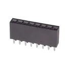
| Project description | Headers & Wire Housings REC 1X08P VRT T/H |
| Official description | PCB Mount Receptacle, Vertical, Board-to-Board, 8 Position, 2.54 mm Centerline, Gold (Au), Through Hole - Solder, Signal, Black, AMPMODU IV/V |
| Series | AMPMODU IV/V |
| Mounting / termination | Board mount, through-hole solder |
| Positions / rows | 8 positions, 1 row |
| Pitch | 2.54 mm (0.100 in) |
| Housing | Polyester GF, black, UL 94V-0 |
| Contact material | Phosphor bronze |
| Contact finish | 0.762 µm gold mating area, tin termination area |
| Electrical ratings found | 2 A max per contact, 333 VAC operating voltage |
| Temperature range | -65 to 105 °C |
| Datasheet/customer drawing URL present | Yes |
Extracted metadata
| Category | Extracted data |
|---|---|
| Part identity | 5-534237-6, TE internal description 08 MODII VRT SR CE 100/115 |
| Product type | PCB mount receptacle, board-to-board, vertical, closed top entry |
| Positions | 8 |
| Rows | 1 |
| Pitch | 2.54 mm (0.100 in) |
| Termination | Through Hole - Solder |
| Contact current rating | 2 A max |
| Operating voltage | 333 VAC |
| Operating temperature | -65 to 105 °C |
| Housing material | Glass-filled polyester |
| Housing color | Black |
| Flammability | UL 94V-0 |
| Contact material | Phosphor bronze |
| Mating area plating | Gold (Au), 0.762 µm (30 µin) |
| PCB tail plating | Tin, 150 µin |
| Compliance note | RoHS compliant |
| Applicable docs referenced | Product spec 108-25022, application spec 114-25018 |
Absolute maximum ratings
| Item | Result |
|---|---|
| Absolute maximum ratings table | Not present in the TE customer drawing |
| Practical consequence | This document is primarily mechanical / product-definition data, not a full abs-max table document |
Recommended operating conditions
| Item | Result |
|---|---|
| Operating temperature range | -65 to 105 °C |
| Current rating | 2 A max per contact |
| Voltage rating | 333 VAC |
| Recommended PCB pitch | 2.54 mm |
| Recommended PCB hole diameter | 1.02 mm |
| Wire size / insulation diameter | Not found in the customer drawing for this exact vertical PCB-mount receptacle page set |
Pin descriptions
| Pin info type | Result |
|---|---|
| Pin count in project | 8 |
| Numbering present on housing | Yes |
| Functional per-pin descriptions | Not provided |
| Available pin definition from official docs | Positions are numbered cavities 1 through 8; no distinct electrical function per pin because this is a passive receptacle |
Package / mechanical dimensions
| Dimension | Result |
|---|---|
| Overall length | 20.32 mm (0.800 in) |
| Pitch span B | 17.78 mm (0.700 in) |
| Body width callout found from drawing/footprint correlation | About 3.56 mm (0.140 in) |
| Above-board height / body envelope evidence | Customer-drawing extraction was inconsistent, but the footprint asset name encodes 20.32 x 3.56 x 8.64 mm, which aligns with the library footprint body model naming |
| Recommended hole diameter | 1.02 mm |
| Board pitch | 2.54 mm |
Special features / notes
| Feature | Result |
|---|---|
| Connector family | AMPMODU IV/V |
| Entry style | Closed, top entry |
| Mounting style | Vertical |
| Position marking | Cavity numbers marked on housing |
| Notes from drawing | Non-cumulative tolerances, cavity-centerline note, molded logo/date-code notes |
Cross-check results
| Check | Project | Official data | Status | Risk |
|---|---|---|---|---|
| Pin count | 8 | 8 | Pass | Low |
| Pitch | Footprint asset name indicates 2.54 mm | 2.54 mm | Pass | Low |
| Single-row format | Footprint asset name indicates 1x8 | 1 row, 8 pos | Pass | Low |
| Pad numbering | Pads 1-8 | Positions 1-8 | Pass | Low |
| Pin 1 identification | Pad 1 is rectangular | Standard orientation cue present | Pass | Low |
| Drill size | 0.95 mm | Recommended 1.02 mm hole | Pass, but tight | Medium |
| Drill tolerance margin | 0.95 mm lies within 0.94 mm to 1.10 mm implied range | Near low limit | Caution | Medium |
| Footprint body length | Fab outline spans about 20.32 mm | 20.32 mm | Pass | Low |
| Schematic pin typing | Pins are effectively unspecified terminals | Passive connector positions | Incomplete metadata | Low to Medium |
| Datasheet type | Customer drawing, not full parametric datasheet | Official but mechanically focused | Caution | Medium |
Manufacturing / ordering / failure-risk findings
| Finding | Why it matters |
|---|---|
| The footprint drill is tight at 0.95 mm versus the 1.02 mm recommended hole. | It is still inside the extracted tolerance window, but very close to the lower limit. This can reduce assembly margin if plating thickness, drill tolerance, or lead variation stack unfavorably. |
| The current document on the part is a customer drawing, not a full all-in-one datasheet. | Good enough for footprint/order identity, but weaker for complete library metadata coverage. |
| Symbol pin metadata is sparse. | The schematic side is usable, but undefined pin types can reduce ERC quality and part usability in larger designs. |
| I found no evidence of a pin-count or pitch mismatch. | That removes the biggest board-failure risk. |
| I found no obvious ordering mismatch between the part project and the official TE product page. | The project MPN, position count, family, and vertical through-hole style align. |
Bottom line
| Verdict | Summary |
|---|---|
| Overall | Mostly correct |
| Main concern | Footprint hole diameter is slightly undersized relative to the recommended 1.02 mm nominal hole |
| Severity | Medium caution, not an immediate hard fail |
| Best next fix | Increase drill to the TE-recommended value if you want more manufacturing margin, and enrich the part metadata with the official TE product-page parameters / linked application spec references. |
Ready.
Reviews

- Wirelessly connects nets on schematic. Used to organize schematics and separate functional blocks. To wirelessly connect net portals, give them same designator. #portaljharwinbarrozo43.0M
- Wirelessly connects power nets on schematic. Identical to the net portal, but with a power symbol. Used to organize schematics and separate functional blocks. To wirelessly connect power net portals, give them the same designator. #portal #powerjharwinbarrozo11.4M
- A generic fixed resistor for rapid developing circuit topology. Save precious design time by seamlessly add more information to this part (value, footprint, etc.) as it becomes available. Standard resistor values: 1.0Ω 10Ω 100Ω 1.0kΩ 10kΩ 100kΩ 1.0MΩ 1.1Ω 11Ω 110Ω 1.1kΩ 11kΩ 110kΩ 1.1MΩ 1.2Ω 12Ω 120Ω 1.2kΩ 12kΩ 120kΩ 1.2MΩ 1.3Ω 13Ω 130Ω 1.3kΩ 13kΩ 130kΩ 1.3MΩ 1.5Ω 15Ω 150Ω 1.5kΩ 15kΩ 150kΩ 1.5MΩ 1.6Ω 16Ω 160Ω 1.6kΩ 16kΩ 160kΩ 1.6MΩ 1.8Ω 18Ω 180Ω 1.8KΩ 18kΩ 180kΩ 1.8MΩ 2.0Ω 20Ω 200Ω 2.0kΩ 20kΩ 200kΩ 2.0MΩ 2.2Ω 22Ω 220Ω 2.2kΩ 22kΩ 220kΩ 2.2MΩ 2.4Ω 24Ω 240Ω 2.4kΩ 24kΩ 240kΩ 2.4MΩ 2.7Ω 27Ω 270Ω 2.7kΩ 27kΩ 270kΩ 2.7MΩ 3.0Ω 30Ω 300Ω 3.0KΩ 30KΩ 300KΩ 3.0MΩ 3.3Ω 33Ω 330Ω 3.3kΩ 33kΩ 330kΩ 3.3MΩ 3.6Ω 36Ω 360Ω 3.6kΩ 36kΩ 360kΩ 3.6MΩ 3.9Ω 39Ω 390Ω 3.9kΩ 39kΩ 390kΩ 3.9MΩ 4.3Ω 43Ω 430Ω 4.3kΩ 43KΩ 430KΩ 4.3MΩ 4.7Ω 47Ω 470Ω 4.7kΩ 47kΩ 470kΩ 4.7MΩ 5.1Ω 51Ω 510Ω 5.1kΩ 51kΩ 510kΩ 5.1MΩ 5.6Ω 56Ω 560Ω 5.6kΩ 56kΩ 560kΩ 5.6MΩ 6.2Ω 62Ω 620Ω 6.2kΩ 62KΩ 620KΩ 6.2MΩ 6.8Ω 68Ω 680Ω 6.8kΩ 68kΩ 680kΩ 6.8MΩ 7.5Ω 75Ω 750Ω 7.5kΩ 75kΩ 750kΩ 7.5MΩ 8.2Ω 82Ω 820Ω 8.2kΩ 82kΩ 820kΩ 8.2MΩ 9.1Ω 91Ω 910Ω 9.1kΩ 91kΩ 910kΩ 9.1MΩ #generics #CommonPartsLibraryjharwinbarrozo1.5M
- A generic fixed capacitor ideal for rapid circuit topology development. You can choose between polarized and non-polarized types, its symbol and the footprint will automatically adapt based on your selection. Supported options include standard SMD sizes for ceramic capacitors (e.g., 0402, 0603, 0805), SMD sizes for aluminum electrolytic capacitors, and through-hole footprints for polarized capacitors. Save precious design time by seamlessly add more information to this part (value, footprint, etc.) as it becomes available. Standard capacitor values: 1.0pF 10pF 100pF 1000pF 0.01uF 0.1uF 1.0uF 10uF 100uF 1000uF 10,000uF 1.1pF 11pF 110pF 1100pF 1.2pF 12pF 120pF 1200pF 1.3pF 13pF 130pF 1300pF 1.5pF 15pF 150pF 1500pF 0.015uF 0.15uF 1.5uF 15uF 150uF 1500uF 1.6pF 16pF 160pF 1600pF 1.8pF 18pF 180pF 1800pF 2.0pF 20pF 200pF 2000pF 2.2pF 22pF 20pF 2200pF 0.022uF 0.22uF 2.2uF 22uF 220uF 2200uF 2.4pF 24pF 240pF 2400pF 2.7pF 27pF 270pF 2700pF 3.0pF 30pF 300pF 3000pF 3.3pF 33pF 330pF 3300pF 0.033uF 0.33uF 3.3uF 33uF 330uF 3300uF 3.6pF 36pF 360pF 3600pF 3.9pF 39pF 390pF 3900pF 4.3pF 43pF 430pF 4300pF 4.7pF 47pF 470pF 4700pF 0.047uF 0.47uF 4.7uF 47uF 470uF 4700uF 5.1pF 51pF 510pF 5100pF 5.6pF 56pF 560pF 5600pF 6.2pF 62pF 620pF 6200pF 6.8pF 68pF 680pF 6800pF 0.068uF 0.68uF 6.8uF 68uF 680uF 6800uF 7.5pF 75pF 750pF 7500pF 8.2pF 82pF 820pF 8200pF 9.1pF 91pF 910pF 9100pF #generics #CommonPartsLibraryjharwinbarrozo1.5M
- A generic fixed inductor for rapid developing circuit topology. *You can now change the footprint and 3D model at the top level anytime you want. This is the power of #genericsjharwinbarrozo15.6k
- An electrical connector acting as reusable interface to a conductor and creating a point where external circuits can be connected.Terminal
- 47 kOhms ±5% 0.125W, 1/8W Chip Resistor 0805 (2012 Metric) Automotive AEC-Q200 Thick Film #forLedBlinkjharwinbarrozo1.2M
- 10uF Capacitor Aluminum Polymer 20% 16V SMD 5x5.3mm #forLedBlink #commonpartslibrary #capacitor #aluminumpolymer #radialcanjharwinbarrozo1.2M
- Yellow 595nm LED Indication - Discrete 1.7V 1206 (3216 Metric) #forLedBlinkjharwinbarrozo1.1M


Pricing & Availability
See prices from popular manufacturers for your project.
Assets
5-534237-6
5-534237-6.stp3D Model
5-534237-6
5-534237-6 Symbol.svgDefault5-534237-6
RHDR8W76P0X254_1X8_2032X356X864P.kicad_modFootprint
5-534237-6.png
5-534237-6ThumbnailControls
Welcome 👋
Flux accelerates your PCB design with AI.
Create your account to start using this component and bring your ideas to life.