Part Datasheet Validation
Thought for 8 mins 21 sec
I completed the review in order.
1) Part information currently present in this part project
Project Metadata Summary
Table
| Field | Value |
|---|---|
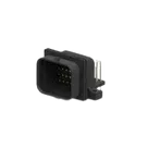
| MPN | 2-6437285-8 |
| Manufacturer | TE Connectivity |
| Part type | Connector |
| Mount | PCB |
| Description | 1.0 mm Header, Superseal 1.0, 26 way, 1 key (4 row), black, 90° molded gold pins, PCB mount, double locking |
| Positions | 26 |
| Rows | 4 |
| Orientation | Horizontal / Right Angle |
| Mating pin diameter | 1.0 mm |
| Contact plating | Gold |
| Connector length | 39.6 mm |
| Connector width | 23 mm |
| Profile height from PCB | 21.4 mm |
| Datasheet URL present? | Yes |
| Datasheet URL | https://www.te.com/commerce/DocumentDelivery/DDEController?Action=srchrtrv&DocNm=1-1773962-8&DocType=Data%20Sheet&DocLang=English&PartCntxt=2-6437285-8&DocFormat=pdf |
Table
| Item | Observed |
|---|---|
| Symbol implementation | Built from 26 separate one-pin schematic primitives |
| Pin count in schematic | 26 |
| Visible numbering | 1 through 26 |
| Nets defined | None |
| Pin electrical types | Unspecified on all visible symbol primitives |
| BOM identity | Current BOM shows a generic terminal-style construction rather than a clean single connector BOM entry |
A datasheet URL is already set, so no web lookup or property update was needed.
3) Datasheet scan and extracted metadata
I scanned the available TE documentation tied to this MPN and cross-referenced the official TE catalog/product references.
Product Identity and Features
Table
| Field | Datasheet / TE docs result |
|---|---|
| Part number | 2-6437285-8 |
| TE internal description | SUPER SEAL 26POS CAP ASSY H AU |
| Family | AMP SUPERSEAL 1.0 |
| Product style | Header |
| Configuration | 26 position, 4 row, key type 1 |
| Orientation | Right Angle / 90° |
| PCB termination | Through Hole - Solder |
| Mounting holes | With |
| Locking | Double locking |
| Sealable | Yes |
| Application area | Industrial & commercial transportation |
Table
| Parameter | Value |
|---|---|
| Contact current rating | up to 13 A |
| Voltage rating | 24 V DC |
| Insulation resistance | 100 MΩ minimum |
| Dielectric withstanding voltage | 1500 V AC |
| Operating temperature | -40°C to +125°C |
| Flammability | UL 94 V0 |
Table
| Parameter | Value |
|---|---|
| Number of positions | 26 |
| Number of rows | 4 |
| Contact type | Pin |
| Mating pin diameter | 1 mm [.039 in] |
| Centerline (pitch) | 3 mm / 3.5 mm [.118 in / .138 in] |
| Connector length | 39.6 mm [1.56 in] |
| Connector width | 23 mm [.906 in] |
| Profile height from PCB | 21.4 mm [.843 in] |
| Overall height (catalog) | 31.4 mm [1.23 in] |
| Overall length 90° (catalog) | 36.5 mm [1.44 in] |
Table
| Field | Value |
|---|---|
| Mateable plug housing | 2-1437285-2 |
Table
| Document type | Document name |
|---|---|
| Product drawing | JPN_CD_2-6437285-8_A.pdf |
| CAD | ENG_CVM_CVM_2-6437285-8_C.2d_dxf.zip |
| 3D PDF | 3D_CVM_CVM_2-6437285-8_C.pdf |
| Application specification | ENG_SS_114-78011_A1.pdf |
| Product specification | ENG_SS_108-78140_A9.pdf |
Table
| Item | Result |
|---|---|
| Per-pin functional descriptions | Not found in the accessible selector/catalog datasheet |
| Pin numbering / cavity numbering table | Not found in the accessible selector/catalog datasheet text |
| What is confirmed | The part is 26 position / 4 row and the symbol currently exposes pins 1-26 |
Table
| Category | Result |
|---|---|
| Absolute Maximum Ratings table | Not present in the accessible selector/catalog datasheet |
| Recommended Operating Conditions table | Not present as a formal table |
| Closest usable operating limit | Operating temperature: -40°C to +125°C |
| Electrical withstand / insulation limits available | Yes |
Table
| Check | Status | Risk |
|---|---|---|
| Pin count matches datasheet | Pass | Low |
| 4-row / 26-position intent matches part metadata | Pass | Low |
| Right-angle through-hole intent matches part metadata | Pass | Low |
| Clean single-connector symbol definition | Fail / incomplete | Medium |
| Pin electrical typing defined | Fail | Medium |
| Per-pin names/descriptions mapped from manufacturer docs | Not verified | Medium |
| Exact PCB hole pattern / drill sizes verified against product drawing | Not verified | High |
| Exact pad geometry verified | Not verified | High |
| Footprint dimensions fully verified from manufacturer drawing | Not verified | High |
| Clean BOM identity for ordering | Fail / incomplete | High |
Table
| Issue | Why it matters |
|---|---|
| The symbol is built as 26 separate one-pin primitives instead of a clean connector part definition | This can create weak BOM identity, harder reuse, and more error-prone pin management. |
| All visible symbol pins are effectively unspecified electrical type | ERC quality is reduced and connection mistakes are easier to miss. |
| The current project/BOM view does not expose a clean package/footprint name or package code | This increases the chance of ordering or library confusion. |
| I could not verify drill diameters, pad diameters, exact row spacing implementation, and mounting-hole geometry from the available accessible datasheet text alone | That is the main manufacturing-risk gap. A mismatch here could cause assembly or fit failure. |
| I could not extract an official pin numbering/cavity layout drawing from the accessible text | If the footprint numbering order differs from the mating face numbering, the board could be electrically wrong even if the pin count is correct. |
Table
| Area | Conclusion |
|---|---|
| Part identity | Looks consistent with TE 2-6437285-8 |
| Basic symbol size/count | Looks broadly correct: 26 pins |
| Manufacturing readiness | Not fully verified |
| Highest-risk unresolved item | Footprint geometry and numbering vs. TE product drawing |
The most important next verification artifact is the official product drawing for 2-6437285-8 because that is what will confirm:
- exact hole locations
- drill sizes
- mounting-hole geometry
- cavity numbering orientation
- mating-face numbering convention
Right now, the part is partially validated, but I would not consider the footprint fully signed off for manufacturing from the accessible docs alone.
Check exact footprint
Review BOM identity
Find drawing link


Welcome 👋
Flux accelerates your PCB design with AI.
Create your account to start using this component and bring your ideas to life.