Part Datasheet Validation
Thought for 8 mins 21 sec
I completed the review in order.
1) Part information currently present in this part project
Project Metadata Summary
Table
| Field | Value |
|---|---|
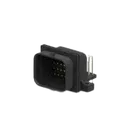
| MPN | 2-6437285-8 |
| Manufacturer | TE Connectivity |
| Part type | Connector |
| Mount | PCB |
| Description | 1.0 mm Header, Superseal 1.0, 26 way, 1 key (4 row), black, 90° molded gold pins, PCB mount, double locking |
| Positions | 26 |
| Rows | 4 |
| Orientation | Horizontal / Right Angle |
| Mating pin diameter | 1.0 mm |
| Contact plating | Gold |
| Connector length | 39.6 mm |
| Connector width | 23 mm |
| Profile height from PCB | 21.4 mm |
| Datasheet URL present? | Yes |
| Datasheet URL | https://www.te.com/commerce/DocumentDelivery/DDEController?Action=srchrtrv&DocNm=1-1773962-8&DocType=Data%20Sheet&DocLang=English&PartCntxt=2-6437285-8&DocFormat=pdf |
Table
| Item | Observed |
|---|---|
| Symbol implementation | Built from 26 separate one-pin schematic primitives |
| Pin count in schematic | 26 |
| Visible numbering | 1 through 26 |
| Nets defined | None |
| Pin electrical types | Unspecified on all visible symbol primitives |
| BOM identity | Current BOM shows a generic terminal-style construction rather than a clean single connector BOM entry |
A datasheet URL is already set, so no web lookup or property update was needed.
3) Datasheet scan and extracted metadata
I scanned the available TE documentation tied to this MPN and cross-referenced the official TE catalog/product references.
Product Identity and Features
Table
| Field | Datasheet / TE docs result |
|---|---|
| Part number | 2-6437285-8 |
| TE internal description | SUPER SEAL 26POS CAP ASSY H AU |
| Family | AMP SUPERSEAL 1.0 |
| Product style | Header |
| Configuration | 26 position, 4 row, key type 1 |
| Orientation | Right Angle / 90° |
| PCB termination | Through Hole - Solder |
| Mounting holes | With |
| Locking | Double locking |
| Sealable | Yes |
| Application area | Industrial & commercial transportation |
Table
| Parameter | Value |
|---|---|
| Contact current rating | up to 13 A |
| Voltage rating | 24 V DC |
| Insulation resistance | 100 MΩ minimum |
| Dielectric withstanding voltage | 1500 V AC |
| Operating temperature | -40°C to +125°C |
| Flammability | UL 94 V0 |
Table
| Parameter | Value |
|---|---|
| Number of positions | 26 |
| Number of rows | 4 |
| Contact type | Pin |
| Mating pin diameter | 1 mm [.039 in] |
| Centerline (pitch) | 3 mm / 3.5 mm [.118 in / .138 in] |
| Connector length | 39.6 mm [1.56 in] |
| Connector width | 23 mm [.906 in] |
| Profile height from PCB | 21.4 mm [.843 in] |
| Overall height (catalog) | 31.4 mm [1.23 in] |
| Overall length 90° (catalog) | 36.5 mm [1.44 in] |
Table
| Field | Value |
|---|---|
| Mateable plug housing | 2-1437285-2 |
Table
| Document type | Document name |
|---|---|
| Product drawing | JPN_CD_2-6437285-8_A.pdf |
| CAD | ENG_CVM_CVM_2-6437285-8_C.2d_dxf.zip |
| 3D PDF | 3D_CVM_CVM_2-6437285-8_C.pdf |
| Application specification | ENG_SS_114-78011_A1.pdf |
| Product specification | ENG_SS_108-78140_A9.pdf |
Table
| Item | Result |
|---|---|
| Per-pin functional descriptions | Not found in the accessible selector/catalog datasheet |
| Pin numbering / cavity numbering table | Not found in the accessible selector/catalog datasheet text |
| What is confirmed | The part is 26 position / 4 row and the symbol currently exposes pins 1-26 |
Table
| Category | Result |
|---|---|
| Absolute Maximum Ratings table | Not present in the accessible selector/catalog datasheet |
| Recommended Operating Conditions table | Not present as a formal table |
| Closest usable operating limit | Operating temperature: -40°C to +125°C |
| Electrical withstand / insulation limits available | Yes |
Table
| Check | Status | Risk |
|---|---|---|
| Pin count matches datasheet | Pass | Low |
| 4-row / 26-position intent matches part metadata | Pass | Low |
| Right-angle through-hole intent matches part metadata | Pass | Low |
| Clean single-connector symbol definition | Fail / incomplete | Medium |
| Pin electrical typing defined | Fail | Medium |
| Per-pin names/descriptions mapped from manufacturer docs | Not verified | Medium |
| Exact PCB hole pattern / drill sizes verified against product drawing | Not verified | High |
| Exact pad geometry verified | Not verified | High |
| Footprint dimensions fully verified from manufacturer drawing | Not verified | High |
| Clean BOM identity for ordering | Fail / incomplete | High |
Table
| Issue | Why it matters |
|---|---|
| The symbol is built as 26 separate one-pin primitives instead of a clean connector part definition | This can create weak BOM identity, harder reuse, and more error-prone pin management. |
| All visible symbol pins are effectively unspecified electrical type | ERC quality is reduced and connection mistakes are easier to miss. |
| The current project/BOM view does not expose a clean package/footprint name or package code | This increases the chance of ordering or library confusion. |
| I could not verify drill diameters, pad diameters, exact row spacing implementation, and mounting-hole geometry from the available accessible datasheet text alone | That is the main manufacturing-risk gap. A mismatch here could cause assembly or fit failure. |
| I could not extract an official pin numbering/cavity layout drawing from the accessible text | If the footprint numbering order differs from the mating face numbering, the board could be electrically wrong even if the pin count is correct. |
Table
| Area | Conclusion |
|---|---|
| Part identity | Looks consistent with TE 2-6437285-8 |
| Basic symbol size/count | Looks broadly correct: 26 pins |
| Manufacturing readiness | Not fully verified |
| Highest-risk unresolved item | Footprint geometry and numbering vs. TE product drawing |
The most important next verification artifact is the official product drawing for 2-6437285-8 because that is what will confirm:
- exact hole locations
- drill sizes
- mounting-hole geometry
- cavity numbering orientation
- mating-face numbering convention
Right now, the part is partially validated, but I would not consider the footprint fully signed off for manufacturing from the accessible docs alone.
Check exact footprint
Review BOM identity
Find drawing link
To get started, talk to Flux or create a New Document.


Welcome 👋
Flux accelerates your PCB design with AI.
Create your account to start using this component and bring your ideas to life.