Part Verification and Datasheet Review
0:54
Review.
Organ.
Using Schematic Tool.
Using BOM Tool.
Using PCB Layout Tool.
Looking for "part description, product series, number of circuits, pitch, orientation, mounting style, plating, and housing material" in 1719740004_sd.pdf
Looking for "electrical characteristics including voltage rating, current rating, contact resistance, insulation resistance, dielectric withstanding voltage, and temperature range" in 1719740004_sd.pdf
Looking for "absolute maximum ratings" in 1719740004_sd.pdf
Looking for "recommended operating conditions or operating temperature range" in 1719740004_sd.pdf
Looking for "pin numbering, circuit numbering, and any pin or terminal identification details" in 1719740004_sd.pdf
Looking for "package dimensions including overall body dimensions, hole pattern, tail length, and recommended PCB layout dimensions" in 1719740004_sd.pdf
Looking for "special features, key notes, mating information, and application restrictions" in 1719740004_sd.pdf
Part information review
| Field | Result |
|---|---|
| MPN | 171974-0004 |
| Manufacturer | Molex |
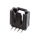
| Description | 2.54 mm pitch SL header, single-row, right-angle, shrouded, through-hole, 4 circuits |
| Mount | Through Hole |
| Part type | Connector |
| Circuit count | 4 |
| Pitch | 2.54 mm |
| Orientation | Right-angle |
| Housing material | LCP, UL94V-0, black |
| Terminal material | Brass |
| Finish | Matte tin over nickel |
| Datasheet property | Already present: Datasheet |
| Schematic symbol | 4 numbered terminals: 1, 2, 3, 4 |
| Footprint asset | SHDR4W97P0X254_1X4_1262X1359X700P.kicad_mod |
| 3D model | Present |
Datasheet metadata summary
| Category | Extracted data |
|---|---|
| Electrical characteristics | 250 V rating, 3.0 A rating, 30 mΩ max initial contact resistance, 1000 MΩ min insulation resistance |
| Dielectric withstand | {2 × rated voltage + 1000 V} VAC for 1 minute between adjacent terminals and terminal-to-ground, with no breakdown |
| Temperature range | -40 °C to +105 °C |
| Absolute maximum ratings | No explicit absolute maximum ratings table was found in the drawing/package document |
| Recommended operating conditions | No dedicated operating-conditions table found; the drawing specifies recommended PCB thickness = 1.57 mm |
| Mating information | Mates with option “G” 70400 and 70430 series SL connectors |
| Solderability / standards | Solderability per SMES-152 lead free alloy |
| Product / packaging specs referenced | 1719710000-PS, PS-70400, packaging per 1719740000-PK |
Pin description check
| Item | Result |
|---|---|
| Pin numbering in datasheet | Circuits are numbered, with Circuit 1 identified on the drawing |
| Pin names/functions | This is a passive connector; no unique signal-function pin names are defined in the datasheet beyond circuit numbering |
| Project symbol | Matches the expected simple numbered-circuit representation: 1, 2, 3, 4 |
Package and PCB dimensions
| Dimension / feature | Datasheet |
|---|---|
| Body length A | 12.62 mm |
| Pattern length B for 4 circuits | 7.62 mm |
| Overall height shown | 13.59 mm |
| Pitch | 2.54 mm typ |
| PCB hole diameter | 1.09 ± 0.08 mm |
| Recommended PCB thickness | 1.57 mm |
| Tail length | 2.90 mm REF |
| Restricted area | 7.0 mm typ |
| PCB layout view | Component side |
Cross-check: symbol and footprint vs datasheet
| Check | Result | Risk |
|---|---|---|
| Circuit count | Symbol has 4 terminals and footprint has 4 pads | No issue |
| Numbering continuity | Symbol and footprint both use 1-4 numbering | No issue |
| Pitch | Footprint pad pitch is 2.54 mm | Matches datasheet |
| Span for 4 circuits | Footprint end-to-end pin span is 7.62 mm | Matches datasheet |
| Drill size | Footprint uses 1.15 mm drill vs datasheet 1.09 ± 0.08 mm | Acceptable, within datasheet tolerance band |
| Pad style | Pin 1 rectangular, others circular | Good for pin-1 identification |
| Package envelope | Footprint naming and courtyard/body dimensions align with 12.62 mm body length and 13.59 mm height shown in datasheet | Looks consistent |
| 3D model presence | Present | Good |
| Datasheet linkage | Already set | Good |
Mismatches / issues flagged
| Issue | Severity | Why it matters |
|---|---|---|
| Symbol terminals are typed as Unspecified instead of passive connector terminals | Low | Could weaken ERC clarity, but not a manufacturing or ordering blocker |
| No explicit per-pin descriptions beyond circuit numbers | Low | Fine for a passive header, but adding clearer terminal metadata could improve reuse |
| No obvious footprint mismatch found | None | I did not find a manufacturing-critical geometry conflict |
| No obvious ordering mismatch found | None | Project MPN and datasheet agree on 171974-0004 |
- The part project already had a valid datasheet URL, so no web lookup or property update was needed.
- The symbol, pad count, numbering, pitch, and hole sizing all appear consistent with the Molex drawing.
- I found no manufacturing-critical mismatch and no obvious wrong-part ordering risk.
- The only cleanup worth considering is improving terminal metadata from Unspecified to passive-style connector semantics for better library quality and ERC behavior.
Ready.
Reviews

- Wirelessly connects nets on schematic. Used to organize schematics and separate functional blocks. To wirelessly connect net portals, give them same designator. #portaljharwinbarrozo43.0M
- Wirelessly connects power nets on schematic. Identical to the net portal, but with a power symbol. Used to organize schematics and separate functional blocks. To wirelessly connect power net portals, give them the same designator. #portal #powerjharwinbarrozo11.4M
- A generic fixed resistor for rapid developing circuit topology. Save precious design time by seamlessly add more information to this part (value, footprint, etc.) as it becomes available. Standard resistor values: 1.0Ω 10Ω 100Ω 1.0kΩ 10kΩ 100kΩ 1.0MΩ 1.1Ω 11Ω 110Ω 1.1kΩ 11kΩ 110kΩ 1.1MΩ 1.2Ω 12Ω 120Ω 1.2kΩ 12kΩ 120kΩ 1.2MΩ 1.3Ω 13Ω 130Ω 1.3kΩ 13kΩ 130kΩ 1.3MΩ 1.5Ω 15Ω 150Ω 1.5kΩ 15kΩ 150kΩ 1.5MΩ 1.6Ω 16Ω 160Ω 1.6kΩ 16kΩ 160kΩ 1.6MΩ 1.8Ω 18Ω 180Ω 1.8KΩ 18kΩ 180kΩ 1.8MΩ 2.0Ω 20Ω 200Ω 2.0kΩ 20kΩ 200kΩ 2.0MΩ 2.2Ω 22Ω 220Ω 2.2kΩ 22kΩ 220kΩ 2.2MΩ 2.4Ω 24Ω 240Ω 2.4kΩ 24kΩ 240kΩ 2.4MΩ 2.7Ω 27Ω 270Ω 2.7kΩ 27kΩ 270kΩ 2.7MΩ 3.0Ω 30Ω 300Ω 3.0KΩ 30KΩ 300KΩ 3.0MΩ 3.3Ω 33Ω 330Ω 3.3kΩ 33kΩ 330kΩ 3.3MΩ 3.6Ω 36Ω 360Ω 3.6kΩ 36kΩ 360kΩ 3.6MΩ 3.9Ω 39Ω 390Ω 3.9kΩ 39kΩ 390kΩ 3.9MΩ 4.3Ω 43Ω 430Ω 4.3kΩ 43KΩ 430KΩ 4.3MΩ 4.7Ω 47Ω 470Ω 4.7kΩ 47kΩ 470kΩ 4.7MΩ 5.1Ω 51Ω 510Ω 5.1kΩ 51kΩ 510kΩ 5.1MΩ 5.6Ω 56Ω 560Ω 5.6kΩ 56kΩ 560kΩ 5.6MΩ 6.2Ω 62Ω 620Ω 6.2kΩ 62KΩ 620KΩ 6.2MΩ 6.8Ω 68Ω 680Ω 6.8kΩ 68kΩ 680kΩ 6.8MΩ 7.5Ω 75Ω 750Ω 7.5kΩ 75kΩ 750kΩ 7.5MΩ 8.2Ω 82Ω 820Ω 8.2kΩ 82kΩ 820kΩ 8.2MΩ 9.1Ω 91Ω 910Ω 9.1kΩ 91kΩ 910kΩ 9.1MΩ #generics #CommonPartsLibraryjharwinbarrozo1.5M
- A generic fixed capacitor ideal for rapid circuit topology development. You can choose between polarized and non-polarized types, its symbol and the footprint will automatically adapt based on your selection. Supported options include standard SMD sizes for ceramic capacitors (e.g., 0402, 0603, 0805), SMD sizes for aluminum electrolytic capacitors, and through-hole footprints for polarized capacitors. Save precious design time by seamlessly add more information to this part (value, footprint, etc.) as it becomes available. Standard capacitor values: 1.0pF 10pF 100pF 1000pF 0.01uF 0.1uF 1.0uF 10uF 100uF 1000uF 10,000uF 1.1pF 11pF 110pF 1100pF 1.2pF 12pF 120pF 1200pF 1.3pF 13pF 130pF 1300pF 1.5pF 15pF 150pF 1500pF 0.015uF 0.15uF 1.5uF 15uF 150uF 1500uF 1.6pF 16pF 160pF 1600pF 1.8pF 18pF 180pF 1800pF 2.0pF 20pF 200pF 2000pF 2.2pF 22pF 20pF 2200pF 0.022uF 0.22uF 2.2uF 22uF 220uF 2200uF 2.4pF 24pF 240pF 2400pF 2.7pF 27pF 270pF 2700pF 3.0pF 30pF 300pF 3000pF 3.3pF 33pF 330pF 3300pF 0.033uF 0.33uF 3.3uF 33uF 330uF 3300uF 3.6pF 36pF 360pF 3600pF 3.9pF 39pF 390pF 3900pF 4.3pF 43pF 430pF 4300pF 4.7pF 47pF 470pF 4700pF 0.047uF 0.47uF 4.7uF 47uF 470uF 4700uF 5.1pF 51pF 510pF 5100pF 5.6pF 56pF 560pF 5600pF 6.2pF 62pF 620pF 6200pF 6.8pF 68pF 680pF 6800pF 0.068uF 0.68uF 6.8uF 68uF 680uF 6800uF 7.5pF 75pF 750pF 7500pF 8.2pF 82pF 820pF 8200pF 9.1pF 91pF 910pF 9100pF #generics #CommonPartsLibraryjharwinbarrozo1.5M
- A generic fixed inductor for rapid developing circuit topology. *You can now change the footprint and 3D model at the top level anytime you want. This is the power of #genericsjharwinbarrozo15.6k
- An electrical connector acting as reusable interface to a conductor and creating a point where external circuits can be connected.Terminal
- 47 kOhms ±5% 0.125W, 1/8W Chip Resistor 0805 (2012 Metric) Automotive AEC-Q200 Thick Film #forLedBlinkjharwinbarrozo1.2M
- 10uF Capacitor Aluminum Polymer 20% 16V SMD 5x5.3mm #forLedBlink #commonpartslibrary #capacitor #aluminumpolymer #radialcanjharwinbarrozo1.2M
- Yellow 595nm LED Indication - Discrete 1.7V 1206 (3216 Metric) #forLedBlinkjharwinbarrozo1.1M


Pricing & Availability
See prices from popular manufacturers for your project.
Assets

171974-0004
171974-0004 Symbol.svgDefault171974-0004
SHDR4W97P0X254_1X4_1262X1359X700P.kicad_modFootprint171974-0004
171974-0004.stp3D Model
1719740004-thumb.png
1719740004-thumbThumbnailControls
Welcome 👋
Flux accelerates your PCB design with AI.
Create your account to start using this component and bring your ideas to life.