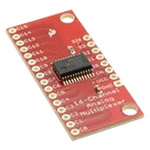
Convert .sch File to Component
Thought for 19 sec
Yes — the
.brd file is useful as a PCB/footprint reference, but it is not the ideal direct-import source for creating a reusable Flux part.From the attachment workflow, Eagle
.brd and .sch files are parsed as EDA design files so they can be used to extract design data and guide migration/reconstruction . But for direct part import, Flux expects EDA library files such as .lbr, .kicad_sym, .kicad_mod, .SchLib, .PcbLib, .IntLib, .json, or .olb .So the practical breakdown is:
Table
| What you want | Best source file | How feasible from .brd |
|---|---|---|
| Recreate the PCB footprint / land pattern | .brd or library footprint file | Good |
| Create a reusable Flux part with symbol + pins + footprint | Library file or datasheet + pin table | Possible, but indirect |
| One-click import as a part | Library file | No, not from .brd alone |
What the
.brd helps with:- Pad geometry
- Hole sizes / drill locations
- Board outline and mechanical spacing
- Placement reference for rebuilding the footprint or breakout board layout concept
What it usually does not solve by itself:
- Clean symbol definition
- Exact pin metadata for a reusable part project
- A direct
@importpath, because that workflow is for library files, not board design files
So the best next step is:
- If you have the matching
.lbrfile, send that too. That is the best path for import. - If not, the
.brd+.sch+ datasheet combination is enough to recreate the part/footprint manually. - If your real goal is just to design a PCB based on this breakout, the
.brdis already a strong reference input for copying the footprint/mechanical layout approach .
If you want, I can next help you choose between:
- rebuilding this as a reusable part, or
- starting a new PCB design using this board as the footprint/mechanical reference.
List library parts
Import breakout parts
Check existing matches
Inspect board contents