MPU-6050 Project Breakdown

1:32

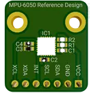
MPU-6050 Reference Design: Detailed Breakdown
This project is a breakout/reference design for the InvenSense MPU-6050 6-axis IMU, providing a ready-to-use I²C interface, power decoupling, and header pins for easy integration into host systems.

1. Purpose & Applications
  • Enable rapid evaluation and integration of the MPU-6050 (3-axis accel + 3-axis gyro) into embedded designs
  • Typical use cases: drones, robotics, motion tracking, stabilization, gesture recognition
  • Offers both primary I²C bus (SDA/SCL) and auxiliary I²C bus (XDA/XCL) for external magnetometer or sensors

2. Core Components & Netlist


DesignatorPartFunction
IC1MPU-60506-axis motion sensor with on-chip regulator
C2Decoupling cap on VDD± capacitive filtering on analog supply
C4Decoupling cap on VLOGICStabilizes digital I/O rail
C3Cap on REGOUTRequired by MPU-6050 internal regulator
C1Cap on CPOUTBypass cap for internal charge pump output
R1I²C pull-up (SCL)4.7 kΩ typical pull-up to 3.3 V
R2I²C pull-up (SDA)4.7 kΩ typical pull-up to 3.3 V
J11×07 2.54 mm headerBreakout: VDD, GND, SDA, SCL, INT, XDA, XCL

3. Functional Blocks & Interactions 3.1 Power & Decoupling
  • 3.3 V In → nets 3V3/3.3V feed both VDD and VLOGIC pins on [IC1]
  • C2 on VDD and C4 on VLOGIC placed as close as possible to the pins
  • Internal LDO: MPU-6050’s on-chip regulator requires C3 (REGOUT→GND) and C1 (CPOUT→GND) per datasheet
3.2 I²C Interface
  • Primary bus: SDA and SCL lines pulled up to 3.3 V by R2 and R1
  • Net routing:
    • SDA net → [IC1:SDA] → [R2] → [J1:Pin 3]
    • SCL net → [IC1:SCL] → [R1] → [J1:Pin 4]
  • Supports up to 400 kHz (or higher “Fast-mode Plus”) if layout and pull-ups are optimized
3.3 Auxiliary I²C & Interrupt
  • Aux bus: XDA/XCL pins broken out to [J1:Pin 7]/[J1:Pin 5] for connecting an external magnetometer or other slave
  • INT (interrupt) pin on [IC1] → [J1:Pin 5] for host to detect data-ready or motion events

4. Design Choices & Trade-offs
  • Internal vs. external regulator
    • Pros: fewer external parts, smaller BOM
    • Cons: limited filtering control—must follow datasheet CPOUT/REGOUT requirements
  • Pull-up resistor value (~4.7 kΩ) balances rise-time vs. I²C drive strength
  • 0603 passives for compactness vs. ease of soldering
  • 2.54 mm header → universal compatibility vs. larger board footprint

5. Layout & Performance Considerations
  • Place decoupling caps within 2 mm of the chip’s VDD/VLOGIC pins
  • Separation of analog (accelerometer/gyro) ground from digital ground if noise becomes an issue—consider split-plane or star ground
  • I²C bus routing: keep SDA/SCL traces parallel, avoid stubs, limit trace length to minimize ringing
  • Optional filtering: ferrite beads or series resistors (22 Ω–33 Ω) on I/O lines for EMI suppression

6. Real-World Challenges
  • Thermal drift affecting sensor accuracy—consider temperature compensation
  • Mechanical vibration → use proper mounting, conformal coating if needed
  • Power-supply noise → add Pi filters or LDO upstream if host rail is noisy

7. Areas for Improvement & Future Enhancements
  • On-board magnetometer (e.g., AK8963) → full 9-axis IMU
  • Level-shifting circuitry for 5 V hosts
  • SPI interface footprint for applications requiring higher-speed data transfer
  • EMI/ESD protection: TVS diodes on I/O pins for robust field deployment
  • Miniaturization: switch to 0201 passives, castellated edges, or castellated dome for module integration

In summary, this reference design adheres to the MPU-6050 datasheet recommendations, providing all necessary decoupling, pull-ups, and breakout access. Proper layout and component selection ensure stable operation up to Fast-mode I²C, enabling seamless integration into motion-sensing applications.
Add magnetometer
Add ESD protection
Decoupling placement
SPI interface footprint
329 days

3V3
3V3
3V3
3V3
C1
Capacitance
2200pF
C3
Capacitance
0.1uF
INT
C2
Capacitance
0.1uF
SCL
SCL
SDA
XCL
SDA
XDA
C4
Capacitance
0.01uF
R2
Resistance
10KΩ
R1
Resistance
10KΩ
IC1


  • Ground
    A common return path for electric current. Commonly known as ground.
  • Net Portal
    Wirelessly connects nets on schematic. Used to organize schematics and separate functional blocks. To wirelessly connect net portals, give them same designator. #portal
  • Power Net Portal
    Wirelessly connects power nets on schematic. Identical to the net portal, but with a power symbol. Used to organize schematics and separate functional blocks. To wirelessly connect power net portals, give them the same designator. #portal #power
  • Generic Resistor
    A generic fixed resistor ideal for rapid circuit topology development. Its footprint automatically adapts based on the selected package case code—supporting 0402, 0603, 0805, 1203, and many other standard SMD packages, as well as axial horizontal and vertical configurations. Save precious design time by seamlessly add more information to this part (value, footprint, etc.) as it becomes available. Standard resistor values: 1.0 ohm, 10 ohm, 100 ohm, 1.0k ohm, 10k ohm, 100k ohm, 1.0M ohm 1.1 ohm, 11 ohm, 110 ohm, 1.1k ohm, 11k ohm, 110k ohm, 1.1M ohm 1.2 ohm, 12 ohm, 120 ohm, 1.2k ohm, 12k ohm, 120k ohm, 1.2M ohm 1.3 ohm, 13 ohm, 130 ohm, 1.3k ohm, 13k ohm, 130k ohm, 1.3M ohm 1.5 ohm, 15 ohm, 150 ohm, 1.5k ohm, 15k ohm, 150k ohm, 1.5M ohm 1.6 ohm, 16 ohm, 160 ohm, 1.6k ohm, 16k ohm, 160k ohm, 1.6M ohm 1.8 ohm, 18 ohm, 180 ohm, 1.8K ohm, 18k ohm, 180k ohm, 1.8M ohm 2.0 ohm, 20 ohm, 200 ohm, 2.0k ohm, 20k ohm, 200k ohm, 2.0M ohm 2.2 ohm, 22 ohm, 220 ohm, 2.2k ohm, 22k ohm, 220k ohm, 2.2M ohm 2.4 ohm, 24 ohm, 240 ohm, 2.4k ohm, 24k ohm, 240k ohm, 2.4M ohm 2.7 ohm, 27 ohm, 270 ohm, 2.7k ohm, 27k ohm, 270k ohm, 2.7M ohm 3.0 ohm, 30 ohm, 300 ohm, 3.0K ohm, 30K ohm, 300K ohm, 3.0M ohm 3.3 ohm, 33 ohm, 330 ohm, 3.3k ohm, 33k ohm, 330k ohm, 3.3M ohm 3.6 ohm, 36 ohm, 360 ohm, 3.6k ohm, 36k ohm, 360k ohm, 3.6M ohm 3.9 ohm, 39 ohm, 390 ohm, 3.9k ohm, 39k ohm, 390k ohm, 3.9M ohm 4.3 ohm, 43 ohm, 430 ohm, 4.3k ohm, 43K ohm, 430K ohm, 4.3M ohm 4.7 ohm, 47 ohm, 470 ohm, 4.7k ohm, 47k ohm, 470k ohm, 4.7M ohm 5.1 ohm, 51 ohm, 510 ohm, 5.1k ohm, 51k ohm, 510k ohm, 5.1M ohm 5.6 ohm, 56 ohm, 560 ohm, 5.6k ohm, 56k ohm, 560k ohm, 5.6M ohm 6.2 ohm, 62 ohm, 620 ohm, 6.2k ohm, 62K ohm, 620K ohm, 6.2M ohm 6.8 ohm, 68 ohm, 680 ohm, 6.8k ohm, 68k ohm, 680k ohm, 6.8M ohm 7.5 ohm, 75 ohm, 750 ohm, 7.5k ohm, 75k ohm, 750k ohm, 7.5M ohm 8.2 ohm, 82 ohm, 820 ohm, 8.2k ohm, 82k ohm, 820k ohm, 8.2M ohm 9.1 ohm, 91 ohm, 910 ohm, 9.1k ohm, 91k ohm, 910k ohm, 9.1M ohm #generics #CommonPartsLibrary
  • Generic Capacitor
    A generic fixed capacitor ideal for rapid circuit topology development. You can choose between polarized and non-polarized types, its symbol and the footprint will automatically adapt based on your selection. Supported options include standard SMD sizes for ceramic capacitors (e.g., 0402, 0603, 0805), SMD sizes for aluminum electrolytic capacitors, and through-hole footprints for polarized capacitors. Save precious design time by seamlessly add more information to this part (value, footprint, etc.) as it becomes available. Standard capacitor values: 1.0pF, 10pF, 100pF, 1000pF, 0.01uF, 0.1uF, 1.0uF, 10uF, 100uF, 1000uF, 10000uF 1.1pF, 11pF, 110pF, 1100pF 1.2pF, 12pF, 120pF, 1200pF 1.3pF, 13pF, 130pF, 1300pF 1.5pF, 15pF, 150pF, 1500pF, 0.015uF, 0.15uF, 1.5uF, 15uF, 150uF, 1500uF 1.6pF, 16pF, 160pF, 1600pF 1.8pF, 18pF, 180pF, 1800pF 2.0pF, 20pF, 200pF, 2000pF 2.2pF, 22pF, 220pF, 2200pF, 0.022uF, 0.22uF, 2.2uF, 22uF, 220uF, 2200uF 2.4pF, 24pF, 240pF, 2400pF 2.7pF, 27pF, 270pF, 2700pF 3.0pF, 30pF, 300pF, 3000pF 3.3pF, 33pF, 330pF, 3300pF, 0.033uF, 0.33uF, 3.3uF, 33uF, 330uF, 3300uF 3.6pF, 36pF, 360pF, 3600pF 3.9pF, 39pF, 390pF, 3900pF 4.3pF, 43pF, 430pF, 4300pF 4.7pF, 47pF, 470pF, 4700pF, 0.047uF, 0.47uF, 4.7uF, 47uF, 470uF, 4700uF 5.1pF, 51pF, 510pF, 5100pF 5.6pF, 56pF, 560pF, 5600pF 6.2pF, 62pF, 620pF, 6200pF 6.8pF, 68pF, 680pF, 6800pF, 0.068uF, 0.68uF, 6.8uF, 68uF, 680uF, 6800uF 7.5pF, 75pF, 750pF, 7500pF 8.2pF, 82pF, 820pF, 8200pF 9.1pF, 91pF, 910pF, 9100pF #generics #CommonPartsLibrary
  • Generic Inductor
    A generic fixed inductor suitable for rapid circuit topology development. The footprint automatically adapts based on the selected package, supporting standard SMD sizes (e.g., 0402, 0603, 0805) as well as well-known inductor packages such as SDR1806, PA4320, SRN6028, and SRR1260. Standard inductor values: 1.0 nH, 10 nH, 100 nH, 1.0 µH, 10 µH, 100 µH, 1.0 mH 1.2 nH, 12 nH, 120 nH, 1.2 µH, 12 µH, 120 µH, 1.2 mH 1.5 nH, 15 nH, 150 nH, 1.5 µH, 15 µH, 150 µH, 1.5 mH 1.8 nH, 18 nH, 180 nH, 1.8 µH, 18 µH, 180 µH, 1.8 mH 2.2 nH, 22 nH, 220 nH, 2.2 µH, 22 µH, 220 µH, 2.2 mH 2.7 nH, 27 nH, 270 nH, 2.7 µH, 27 µH, 270 µH, 2.7 mH 3.3 nH, 33 nH, 330 nH, 3.3 µH, 33 µH, 330 µH, 3.3 mH 3.9 nH, 39 nH, 390 nH, 3.9 µH, 39 µH, 390 µH, 3.9 mH 4.7 nH, 47 nH, 470 nH, 4.7 µH, 47 µH, 470 µH, 4.7 mH 5.6 nH, 56 nH, 560 nH, 5.6 µH, 56 µH, 560 µH, 5.6 mH 6.8 nH, 68 nH, 680 nH, 6.8 µH, 68 µH, 680 µH, 6.8 mH 8.2 nH, 82 nH, 820 nH, 8.2 µH, 82 µH, 820 µH, 8.2 mH #generics #CommonPartsLibrary
  • Terminal
    Terminal
    An electrical connector acting as reusable interface to a conductor and creating a point where external circuits can be connected.
  • RMCF0805JT47K0
    47 kOhms ±5% 0.125W, 1/8W Chip Resistor 0805 (2012 Metric) Automotive AEC-Q200 Thick Film #forLedBlink
  • 875105359001
    10uF Capacitor Aluminum Polymer 20% 16V SMD 5x5.3mm #forLedBlink #commonpartslibrary #capacitor #aluminumpolymer #radialcan
  • CTL1206FYW1T
    Yellow 595nm LED Indication - Discrete 1.7V 1206 (3216 Metric) #forLedBlink

MPU-6050 Reference Design

MPU-6050 Reference Design thumbnail
This is the MPU-6050 IMU reference design. This reference design has a basic I2C circuit for communication built according to the manufacturer's recommendations #IMU #MPU-6050 #I2C #referenceDesign #tdk #template #reference-design

Pricing & Availability

Distributor

Qty 1

Digi-Key

$4.63–$7.16

LCSC

$5.87

Mouser

$8.21

Controls