ESP32-CAM Pin Help

Explain what the selected terminal ESP32-CAM1 does on this part. Describe its function, electrical characteristics, and any special considerations for proper usage.
I’ll inspect ESP32-CAM1’s terminals and its connected net so the explanation matches this exact part instance.
ESP32-CAM1 has 16 terminals, so I can’t determine which one is selected from the project data alone. Please provide the terminal label—such as 5V, 3V3, GND, IO0, IO4, IO1/U0T, or IO3/U0R—and I’ll describe its function, voltage/current characteristics, boot-strapping behavior, and usage precautions.
Explain IO0
Explain 5V
Explain 3V3
Explain UART pins
Explain all pins
please explain what J5 does.

Someone is typing...
12
explain this project.

Someone is typing...
7
how do I use Flux?

Someone is typing...
4
como puedo conectar un sensor ultrasonico hc-sr04

Someone is typing...
3
New Comment

Someone is typing...
8
What is the component U1?

Someone is typing...
5
What is the component U1?

Someone is typing...
6
create a high level mermaid block diagram of this project. Include key component...

Someone is typing...
11
hence what could b the code

Someone is typing...
10
create a detailed step by step plan table for this project to verify its functio...

Someone is typing...
13
I wanted to create a motherboard for an automatic sensor

Someone is typing...
9
New Comment

Someone is typing...
14
IO16
USBDP
BOOT
ESP_EN
IO4
IO16
IO2
ESP_RX
IO12
IO12
ESP_TX
CC2
USBDN
IO12
IO4
ESP_EN
IO14
USBDN
USBDP
BOOT
CC1
IO13
USBDN
IO2
ESP_EN
IO15
ESP_EN
IO15
BOOT
CC1
IO15
USBDP
ESP_TX
BOOT
IO13
ESP_RX
USBDP
USBDP
IO16
IO14
ESP_RX
ESP_RX
USBDN
ESP_TX
IO2
ESP_TX
CC2
IO14
IO13
IO4
ESP_EN
USBDN
D1
+3V3
IO2
+3V3
VBUS
+5V
ESP_EN
VBUS
IO13
+5V
IO12
+5V
ESP_RX
IO4
+5V
+3V3
+5V
+3V3
GND
IO15
+3V3
+3V3
+3V3
+3V3
+3V3
+5V
GND
+3V3
IO14
ESP_TX
BOOT
IO16
R5
Resistance
0 Ω
D2
R2
Resistance
1kΩ
IC1
R1
Resistance
Resistance
Resistance
5.1kΩ
D4
C2
Capacitance
10uF
R4
Resistance
0 Ω
C6
Capacitance
0.1uF
D3
C7
Capacitance
0.1uF
R3
Resistance
Resistance
Resistance
5.1kΩ
C3
Capacitance
10uF
RST
C4
Capacitance
10uF
U1
J3
J5
J4
ESP32-CAM1
LED1
C5
Capacitance
10uF

No files yet

Documents

    Documents are markdown text files which describe project goals, capture details, or even simulation outputs.

    Assets

    ESP-CAM Motherboard Module-removebg-preview.png

    ESP-CAM Motherboard Module-removebg-preview.png

    ESP-CAM Motherboard Module-removebg-previewThumbnail

    ESP-CAM Motherboard Module

    ESP-CAM Motherboard Module thumbnail
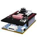
    This project is a motherboard for the ESP32-CAM module, which enables easy and flexible WiFi camera applications. The motherboard provides power supply, programming interface, and GPIO expansion for the ESP32-CAM. It also supports external sensors for more functionality. #motherboard #WiFi #MCU #ReferenceDesign #project #ESP32 #camera #reusable #module #edgeComputing #espressif #template

    Pricing & Availability

    Distributor

    Qty 1

    Digi-Key

    $1.08–$2.28

    LCSC

    $1.66–$1.85

    Mouser

    $1.75

    Controls