Electrical Layout Connection Guide
0:55
Chat History
Project
ESP32-CAM1
Below is a suggested wiring update with explicit component names and the required connections. You can use the "Apply changes" button to incorporate these updates into your schematic.
Component List and Connections:
Table
| Component | Part Name & Link | Function / Connection |
|---|---|---|
| 12V Battery | (Use a net label called Battery_12V) | Supplies 12V to both motor driver and buck converter |
| L298N Motor Driver | L298N Motor Driver | - Motor supply connected to Battery_12V - Logic supply (if required) connected to 5V net |
| Buck Converter | AMS1117-5.0 | Steps down 12V from Battery_12V to 5V |
| ESP32-CAM Module | ESP32-CAM | Receives 5V from the buck converter output and interfaces with L298N through its GPIOs |
| Common Ground | c2e41937-4268-256c-7ae9-cb8cfb60aed3 | All GND pins from ESP32-CAM, L298N, and battery negative → common ground net |
Wiring Details:
- Power Connections:
- Battery 12V Supply:
- Label the battery’s positive terminal with Battery_12V.
- Connect Battery_12V directly to the motor supply input of the L298N Motor Driver.
- Also connect Battery_12V to the input of the AMS1117-5.0 buck converter.
- Buck Converter (AMS1117-5.0):
- The output of the AMS1117-5.0 should be labeled as 5V.
- Connect this 5V net to the power input (VCC) of the ESP32-CAM.
- If the L298N’s logic also requires 5V, connect the 5V net to its logic supply as well.
- Battery 12V Supply:
- Signal Connections between ESP32-CAM and L298N:
- ESP32-CAM → L298N:
- GPIO12 (ESP32-CAM) → IN1 on L298N.
- GPIO13 (ESP32-CAM) → IN2 on L298N.
- GPIO14 (ESP32-CAM) → IN3 on L298N.
- GPIO15 (ESP32-CAM) → IN4 on L298N.
- ESP32-CAM → L298N:
- Ground Connections:
- Connect the ground (GND) pin of the ESP32-CAM, the L298N’s ground, and the battery negative terminal to a common Ground component (c2e41937-4268-256c-7ae9-cb8cfb60aed3).
Additional Notes:
- Ensure that any required decoupling capacitors are added per the datasheet recommendations for the buck converter and both the L298N and ESP32-CAM modules.
- Double-check that the L298N used matches the connection points for motor supply (12V) and logic (5V), as some variants could use separate feeds.
- The above schematic changes assume you add or update these components into your project. You can modify the designators if needed.
Use the "Apply changes" button to update your schematic with these wiring and component connections.
Apply wiring changes
Integrate labeled components
Verify connection names
Review component connection list
336 days
Ready.
explain this project.
1y
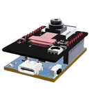
This project is to design an ESP-CAM motherboard module, which serves as an interface board for the ESP32−CAM. This motherboard facilitates various functionalities such as power supply management, programming capability, GPIO expansion, and support for external sensors, making it easier to build WiFi-based camera applications.
Here's a detailed breakdown of the project components and connections:
Components Overview
-
ESP32-CAM Module
- ESP32−CAM: A microcontroller board with integrated camera and WiFi/Bluetooth capabilities.
-
USB to UART Bridge
- CH340C (IC1): Acts as a USB to UART bridge, useful for programming and debugging.
-
Voltage Regulators
- AMS1117−3.3 (U1): Converts 5V input to 3.3V output for the ESP32-CAM.
-
Connectors and Interfaces
- Type-C Connector (J5): USB Type-C connector for power and data.
- Pin Headers (J3, J4): For interfacing with external devices and sensors.
-
Passive Components
- Resistors (R1, R2, R3, R4, R5): Various resistors used in pull-up, pull-down, and current-limiting applications.
- Capacitors (C2, C3, C4, C5, C6, C7): Various decoupling and filtering capacitors.
-
Diodes
- 1N5819HW−7−F (D2): A Schottky diode for reverse polarity protection.
- 1N4148WS−7 (D3, D4): General-purpose switching diodes.
-
LED Indicator
- LED1: For indicating power or status.
-
Push-button Switch
- TL3330AF260QG (RST): Push-button for resetting the ESP32-CAM module.
-
5V Power Input
- Connect +5V to U1:3 (VIN).
- Connect U1:1 (GND) to GND.
- This configuration provides a regulated 3.3V output.
-
3.3V Power Output
- Connect U1:2 (VOUT) to the 3.3V net (also connected to ESP32-CAM1:12 ($3V3$)).
- Decoupling capacitors (C2, C3, C6, C7) are connected between 3.3V and GND for stability.
- For programming the ESP32-CAM:
- CH340C connections:
- IC1:2 (TXD) to R5:2 and ESP32-CAM1:11 ($IO3/U0R$).
- IC1:3 (RXD) to R4:1 and ESP32-CAM1:10 ($IO1/U0T$).
- CH340C connections:
- Header Pin Connections:
- J3 and J4 provide easy access to various GPIO pins of the ESP32-CAM for interfacing with external devices and sensors.
- Connections are made according to the standard pin setup of the ESP32-CAM module as listed.
- For USB communication:
- J5 (Type-C Connector):
- Pin 2 ($DP1$) to IC1:5 ($UD+$).
- Pin 3 ($DN1$) to IC1:6 ($UD-$).
- J5 (Type-C Connector):
-
Reset Button (RST)
- Connect RST:2 to GND.
- Connect RST:1 to ESP_EN net for resetting the ESP32-CAM.
-
LED1
- Connect the anode (A) of LED1 to a GPIO pin (R2:1).
- Connect the cathode (K) to GND.
-
Power Nets (e.g., +5V, +3V3)
- Ensure proper power distribution and decoupling for stable operation.
-
Ground Net (GND)
- Common ground connection for all components to maintain proper functionality.
-
Data and Control Nets
- Specific nets that manage connections between GPIO pins, data lines, and control signals for proper communication and control.
This project, therefore, sets up a comprehensive environment for deploying the ESP32-CAM, providing power regulation, programming capabilities, and extended GPIO access, making it a versatile base for IoT and edge-computing applications.
1y
Someone is typing...
7
how do I use Flux?
HOW TO ADD LED WITH ESP 32 CAM MODULE
1y
@copilot how do I use Flux?
1y
Using Flux to design electronic circuits and lay out PCBs involves several key steps and features. Here's a basic guide to get started and where to find resources for more in-depth learning:
-
First Project: The quickest way to get started is by initiating your first project. This involves creating a new design file in Flux and familiarizing yourself with the interface.
-
Placing Components: You can place components in your schematic by browsing the component library, selecting the components you need, and dragging them onto the canvas.
-
Wiring: After placing your components, you can wire them together using the wiring tools. Make sure to pay attention to the connections to ensure your circuit functions as intended.
-
PCB Layout: Once your schematic is complete, you can switch to PCB layout mode. Here, you transfer your schematic design onto a physical board layout, where you can arrange components and route traces.
-
Verification and Export: Use the built-in tools to verify your design for common errors and export your design files for manufacturing.
For detailed tutorials and resources:
-
Tutorials: Flux offers in-depth tutorials that guide you through various features and tools within the platform. These are great for building specific skills or understanding complex features.
-
YouTube: There are video projects and tutorials available on Flux's YouTube channel, which can be extremely helpful for visual learners.
-
Slack Community: Joining the Flux Slack community allows you to ask questions, share insights, and learn from other users’ experiences.
-
Live Support: If you encounter any issues or have specific questions, you can contact the Flux support team for assistance.
Remember, practice and exploration are key to getting comfortable with Flux. Don’t hesitate to experiment with different features and seek out resources like tutorials and community advice to enhance your skills[1][2][3].
1y
Someone is typing...
4
como puedo conectar un sensor ultrasonico hc-sr04
@copilot si quiero conectar un led que indique que el sensor esta dando una señal como lo conectaria
2y
Para conectar un LED que indique que el sensor está dando una señal, necesitarás algunos componentes adicionales además del LED, como una resistencia para limitar la corriente a través del LED y evitar dañarlo. No mencionas qué sensor específico estás utilizando en tu proyecto, así que voy a suponer que te refieres a una de las señales de los GPIOs disponibles en el módulo ESP32-CAM, por ejemplo, IO4, que ya está en tu diseño.
Aquí hay una manera de conectar un LED para indicar cuando un sensor (o en este caso, una señal de GPIO) está activo:
-
Asegúrate de tener un LED. Los LEDs tienen una polaridad específica: el ánodo (A) es el lado más largo y debe conectarse al voltaje más alto, mientras que el cátodo (K) es el lado más corto y se conecta al voltaje más bajo o a tierra (GND).
-
Elige una resistencia de limitación de corriente adecuada para el LED. Para la mayoría de los LEDs, una resistencia entre 220Ω y 1kΩ funciona bien para voltaje de operación de 3.3V del GPIO. Tomemos 470Ω como valor de la resistencia para este ejemplo, pero necesitarás ajustarlo según las especificaciones de tu LED y el voltaje de operación. Si aún no tienes una resistencia en tu diseño, puedes designarla como R6, por ejemplo.
-
Conexiones a realizar:
- Conecta el ánodo (A) del LED (supongamos que es LED2 con pines A y K) a uno de los GPIOs, por ejemplo, IO4:(P1).
- Conecta el cátodo (K) del LED2 a uno de los pines de la resistencia (supongamos que es R6:P1).
- Conecta el otro pin de la resistencia (R6:P2) a GND. Puedes usar cualquier punto de conexión a tierra disponible en tu diseño, como GND de uno de los pines del ESP32-CAM o un pin GND en el J5 que ya se incluyen en tus redes de tierra.
La configuración quedaría:
- Conecta LED2:A a IO4:P1.
- Conecta LED2:K a R6:1.
- Conecta R6:2 a GND (puedes elegir cualquier GND disponible en tu diseño).
Esto te permitirá encender el LED cuando IO4 esté en alto (proporcionando así señal positiva) y el LED se apagaría cuando IO4 esté en bajo. Recuerda ajustar el GPIO en tu código para que se comporte como deseas (salida y controlado adecuadamente para reflejar el estado del sensor o evento que estás monitoreando).
Si tu sensor ya está ocupando IO4 y operando en esta lógica, esta conexión funcionará. Si necesitas monitorear otro pin o tienes requerimientos específicos, por favor, ajusta las conexiones correspondientemente.
2y
el sensor es el hc-sr 04
2y
El sensor HC-SR04 es un sensor ultrasónico de distancia. Usualmente, este sensor tiene un pin de Trigger (Disparo) para enviar pulsos ultrasónicos y un pin Echo (Eco) para recibir el eco de los pulsos que rebotan en un objeto. El ESP32-CAM no tiene un componente específico HC-SR04 en tu lista de componentes, pero podemos simular su conexión basándonos en cómo operaría usualmente.
Para usar un LED que indique cuando el sensor HC-SR04 está detectando una señal (es decir, cuando recibe un eco dentro de cierta distancia), necesitas conectar el LED de tal manera que se encienda basado en la lógica de la señal del pin Echo.
Suponiendo que:
- Ya has conectado el HC-SR04 a tu ESP32-CAM (por ejemplo, utilizando IO4 para Echo y algún otro GPIO para Trigger).
- Quieres que el LED se encienda cuando el sensor detecta un objeto a una cierta distancia, lo que significa que el pin Echo recibiría un pulso.
Dicho esto, necesitarás implementar la lógica de detección en el firmware del ESP32-CAM para controlar el estado del LED basado en la salida del sensor.
Sin embargo, para el aspecto de conexión, el LED se conectaría básicamente de la misma manera descrita en la respuesta anterior, pero el control del LED (cuándo se enciende y apaga) se realizaría a través del código, monitoreando la salida del pin Echo del HC-SR04.
Aquí está cómo conectar el LED para indicar la activación (detección de objeto) por HC-SR04, asumiendo:
- Usamos IO2 para un LED indicador.
- La resistencia de limitación de corriente del LED es R6 (470 $\Omega$).
Conexiones:
- Conecta el ánodo (A) del LED (designémoslo como LED2) a IO2:P1 (asumiendo que IO2 se configurará como salida y controlará el LED basado en la señal de Echo del HC-SR04).
- Conecta el cátodo (K) de LED2 a R6:1.
- Conecta R6:2 a GND.
El código en el ESP32-CAM necesitará manejar la lógica de:
- Enviar pulsos a través del pin de Trigger del HC-SR04.
- Medir la duración del pulso de retorno en el pin Echo.
- Encender el LED (a través de IO2) si la medida está dentro del rango deseado que indica que un objeto ha sido detectado.
Es importante recordar ajustar la conexión real y el manejo del código según los pines específicos que estás utilizando para conectar el HC-SR04 a tu ESP32-CAM.
2y
si quiero conectar un led que indique que el sensor esta dando una señal como lo conectaria
2y
@copilot como puedo conectar un sensor ultrasonico hc-sr04
2y
Para conectar un sensor ultrasónico HC-SR04 a tu proyecto de ESP32-CAM, necesitarás identificar algunos pines libres en el ESP32-CAM para la señal de Trigger (Disparo) y Echo (Eco). El HC-SR04 generalmente funciona con 5V, pero el ESP32 opera a 3.3V. Esto significa que podríamos necesitar tener en cuenta la diferencia de niveles lógicos para el pin de Echo, pero asumiremos que el sensor y el ESP32-CAM pueden trabajar juntos sin daños.
Basándome en la descripción de tu proyecto, parece que aún tienes algunos pines de entrada/salida (GPIO) disponibles en el ESP32-CAM, como IO2, IO4, IO13, IO14, y IO15. Cada uno de estos pines tiene capacidades diferentes, pero para el propósito simple de controlar el HC-SR04, muchos de ellos pueden servir. Sin embargo, para evitar conflictos con otras funcionalidades (como el arranque del ESP32-CAM), seleccionaré pines que generalmente son seguros para usar:
- Trigger del HC-SR04: Puedes usar
IO4(pin 8 en tu ESP32-CAM), que suele estar libre. - Echo del HC-SR04:
IO2es una opción (pin 7 en tu ESP32-CAM), pero ten en cuenta que IO2 debe estar en alto para arrancar desde la memoria flash. Esto no debería ser un problema después del arranque, pero es algo a considerar.
Aquí tienes las conexiones detalladas:
-
Vcc del HC-SR04 a +5V: Recomiendo conectar el Vcc del HC-SR04 directamente a una salida de +5V en tu placa, para asegurarte de que el sensor reciba el voltaje adecuado. Basándonos en tu descripción, puedes utilizar "+5V:(P1)".
Vcc del HC-SR04a+5V:(P1)
-
GND del HC-SR04 a GND: Asegúrate de conectar el GND del sensor al GND de tu proyecto para tener una referencia de tierra común.
GND del HC-SR04aGND(puedes utilizar cualquier punto de tierra común, comoJ3:(Pin_2).
-
Trigger del HC-SR04 a IO4: Aquí enviarás los pulsos para iniciar el proceso de medición.
Trigger del HC-SR04aESP32-CAM1:(IO4)
-
Echo del HC-SR04 a IO2: Desde este pin recibirás los pulsos de eco, cuya duración es proporcional a la distancia medida.
Echo del HC-SR04aESP32-CAM1:(IO2)
Deberás configurar estos pines en el código que cargues en tu ESP32-CAM para manejar correctamente la comunicación con el sensor HC-SR04. Aún más, considera que IO2 se utiliza comúnmente como un pin de arranque, por lo que podría ser necesario hacer pruebas para asegurar que esta configuración no interfiere con el arranque normal de tu dispositivo.
Si encuentras problemas con la lógica de nivel debido a la diferencia de voltaje entre el sensor (5V) y los pines GPIO del ESP32-CAM (3.3V), podrías necesitar un divisor de tensión o un convertidor de niveles lógicos para el pin de Echo.
2y
Someone is typing...
3
New Comment
Someone is typing...
8
5
6
create a high level mermaid block diagram of this project. Include key component...
1y
Here's a high-level Mermaid block diagram of the ESP32-CAM Motherboard Module project, including the key components and their manufacturer part numbers:
graph TD;

    subgraph ESP32-CAM Motherboard Module
        A[ESP32-CAM]
        subgraph Power Supply
            B1[AMS1117-3.3 - U1] --> B2[ESP32-CAM]
            B3[Input: +5V - J5]
            B1 --> |3.3V Output| B4[CH340C - IC1]
        end

        subgraph Interfaces
            A --> C1[UART Interface]
            C1 --> C2[RX - IC1: RXD]
            C1 --> C3[TX - IC1: TXD]
        end

        subgraph GPIO Expansion
            A --> D1[IO12, IO13, IO14, IO15, IO16, IO2]
            D1 --> |Connection Ports| D2[J3, J4]
        end

        subgraph External Sensors Interface
            A --> E1[Sensor Connections - J3, J4]
        end

        subgraph Status Indicators and Controls
            A --> F1[Boot Button - RST]
            A --> F2[LED Indicator - LED1]
        end

        subgraph Diodes & Capacitors
            G1[1N5819HW-7-F - D2]
            G2[1N4148WS-7 - D3]
            G3[82400102 - D1]
            G4[904002-202 - D4]
            H1[Capacitors C1: node_10uF, C2: node_10uF, C3: 0.1uF]
        end
    end
1y
Someone is typing...
11
hence what could b the code
1y
Certainly! Your project involves creating a motherboard for the ESP32-CAM module. Here is a possible code snippet that you could use to control the ESP32-CAM, assuming you're using the Arduino IDE:
Cpp
#include "esp_camera.h" #include // Replace with your network credentials const char* ssid = "your_SSID"; const char* password = "your_PASSWORD"; void startCameraServer(); // Camera configuration #define PWDN_GPIO_NUM 32 #define RESET_GPIO_NUM -1 #define XCLK_GPIO_NUM 0 #define SIOD_GPIO_NUM 26 #define SIOC_GPIO_NUM 27 #define Y9_GPIO_NUM 35 #define Y8_GPIO_NUM 34 #define Y7_GPIO_NUM 39 #define Y6_GPIO_NUM 36 #define Y5_GPIO_NUM 21 #define Y4_GPIO_NUM 19 #define Y3_GPIO_NUM 18 #define Y2_GPIO_NUM 5 #define VSYNC_GPIO_NUM 25 #define HREF_GPIO_NUM 23 #define PCLK_GPIO_NUM 22 void setup() { Serial.begin(115200); Serial.setDebugOutput(true); Serial.println(); camera_config_t config; config.ledc_channel = LEDC_CHANNEL_0; config.ledc_timer = LEDC_TIMER_0; config.pin_d0 = Y2_GPIO_NUM; config.pin_d1 = Y3_GPIO_NUM; config.pin_d2 = Y4_GPIO_NUM; config.pin_d3 = Y5_GPIO_NUM; config.pin_d4 = Y6_GPIO_NUM; config.pin_d5 = Y7_GPIO_NUM; config.pin_d6 = Y8_GPIO_NUM; config.pin_d7 = Y9_GPIO_NUM; config.pin_xclk = XCLK_GPIO_NUM; config.pin_pclk = PCLK_GPIO_NUM; config.pin_vsync = VSYNC_GPIO_NUM; config.pin_href = HREF_GPIO_NUM; config.pin_sccb_sda = SIOD_GPIO_NUM; config.pin_sccb_scl = SIOC_GPIO_NUM; config.pin_pwdn = PWDN_GPIO_NUM; config.pin_reset = RESET_GPIO_NUM; config.xclk_freq_hz = 20000000; config.pixel_format = PIXFORMAT_JPEG; // Init with high specs to pre-allocate larger buffers if(psramFound()){ config.frame_size = FRAMESIZE_UXGA; config.jpeg_quality = 10; config.fb_count = 2; } else { config.frame_size = FRAMESIZE_SVGA; config.jpeg_quality = 12; config.fb_count = 1; } // Camera init esp_err_t err = esp_camera_init(&config); if (err != ESP_OK) { Serial.printf("Camera init failed with error 0x%x", err); return; } // WiFi connection WiFi.begin(ssid, password); while (WiFi.status() != WL_CONNECTED) { delay(500); Serial.print("."); } Serial.println(""); Serial.println("WiFi connected"); startCameraServer(); Serial.print("Camera Ready! Use 'http://"); Serial.print(WiFi.localIP()); Serial.println("' to connect"); } void loop() { delay(10000); }
This code initializes the ESP32-CAM, connects it to a WiFi network, and starts a basic camera server. Here are the key components that need to be set up in your schematic and how they relate to the code:
Key Components and Connections:
-
Power Supply: Ensure the ESP32-CAM gets a stable 3.3V via the AMS1117-3.3 voltage regulator.
-
Programming Interface: Use the CH340C USB to UART bridge for programming the ESP32-CAM.
-
GPIO Expansion: Ensure the GPIO pins of the ESP32-CAM are accessible and connected properly for your additional components.
-
Camera Pins: Ensure that camera pins are connected as per the pin definitions in the code, e.g., the data pins, XCLK, PCLK, etc.
This should provide a starting point for both the hardware and software aspects of your ESP32-CAM motherboard project. Let me know if you need more details!
1y
Someone is typing...
10
create a detailed step by step plan table for this project to verify its functio...
1y
Certainly! Here's a detailed step-by-step plan table to verify the functionality of your ESP-CAM Motherboard Module project, covering key objectives such as component verification, power supply testing, connectivity checks, and functional tests.
Verification Plan for ESP-CAM Motherboard Module
| Step | Description | Objective | Expected Outcome | Tools/Equipment Needed |
|---|---|---|---|---|
| 1 | Component Inspection | Verify all components visually for damage and correctness. | Components should be physically intact and match the specifications. | Visual inspection tools (magnifying glass, etc.) |
| 2 | Schematic Review | Cross-check schematic against datasheets and connections. | Ensure all connections are logical and match design intentions. | Schematic diagram, datasheets |
| 3 | PCB Assembly Check | Inspect assembled PCB for soldering faults and bridges. | No visible soldering defects or shorts. | Microscope, multimeter |
| 4 | Power Supply Test (Unloaded) | Verify power rails +5V,+3V3 with no load. | Correct voltage levels +5V,+3.3V on respective power rails. | Multimeter |
| 5 | Power Supply Test (Loaded) | Verify power rails with ESP32-CAM and other components. | Stable voltage levels under load conditions. | Multimeter, ESP32-CAM module |
| 6 | Programming Interface Check | Test USB to UART bridge (CH340C) functionality. | Able to flash firmware onto the ESP32-CAM module. | USB cable, terminal software |
| 7 | GPIO Expansion Verification | Check GPIO pins' connectivity and functionality. | Correct voltage levels and switching behavior on GPIO pins. | Multimeter, oscilloscope |
| 8 | Sensor Interface Testing | Verify communication with connected sensors. | Successful data transfer between ESP32-CAM and the sensors. | Relevant sensors, test scripts |
| 9 | Camera Functionality Test | Verify the camera's ability to capture and transmit images. | Clear image capture and transmission over WiFi. | ESP32-CAM module, WiFi network |
| 10 | Reset and BOOT Functionality | Test the reset and boot buttons. | Proper reset and boot behavior of the ESP32-CAM. | Multimeter, oscilloscope |
| 11 | USB Interface Test | Verify USB data lines (USBDP, USBDN) for correct operation. | Successful data communication over USB. | USB cable, logic analyzer |
| 12 | LED Indicators Check | Test LEDs for correct operation (general and status LEDs). | LEDs light up correctly as per design. | Multimeter, power supply |
| 13 | Full System Integration | Test full system functionality with all components working. | ESP32-CAM fully operational, with all peripherals working as intended. | All tools and components integrated |
| 14 | Thermal Testing | Check for overheating during operation. | All components within safe temperature limits. | IR thermometer or thermal camera |
| 15 | Final Verification | Perform a full verification of the system against specs. | Full functionality with no issues. | Comprehensive testing setup |
- Ensure to document each step with measurements and observations for traceability.
- Take corrective actions immediately if any step fails, and re-test the affected step.
- Use suitable personal protective equipment (PPE) and follow standard ESD (Electrostatic Discharge) precautions when handling electronic components.
This plan should help you systematically verify the functionality of your ESP-CAM Motherboard Module project. Let me know if you need further details or specific testing scripts!
1y
Someone is typing...
13
I wanted to create a motherboard for an automatic sensor
1y
That sounds like an exciting project! I assume you want to design a motherboard that can interface with various sensors and automate specific actions based on the sensor data. Given the components and nets in your ESP32-CAM motherboard module project, we need to ensure that your design supports power management, programming interfaces, GPIO expansion, and connections to the external sensors.
Key Requirements
-
Power Supply:
- Ensure that sensors and the ESP32-CAM module have a stable power source.
-
Programming Interface:
- Include USB-to-UART bridge for programming the ESP32.
-
GPIO Expansion:
- Provide connectors or headers for additional GPIO access.
-
Sensor Interface:
- Allow connections to different types of sensors (e.g., digital, analog, I2C, SPI).
Here is an outline of the connections and a list of components for the motherboard:
Power Supply
- U1:AMS1117−3.3 for 3.3V regulation:
- Connect U1:VIN to the 5V input (J5:VBUS).
- Connect U1:GND to ground (GND).
- Connect U1:VOUT to the 3.3V net (+3V3).
- IC1:CH340C for USB-to-UART:
- Connect IC1:RXD to ESP32−CAM1:IO3/U0R via Net 17.
- Connect IC1:TXD to ESP32−CAM1:IO1/U0T via Net 15.
- Connect IC1:UD+ to USBDP:P1.
- Connect IC1:UD− to USBDN:P1.
- Connect IC1:VCC and IC1:V3 to +3V3.
- Connect IC1:GND to ground (GND).
- Headers (like J3) for GPIO connections:
- Ensure various GPIO pins are accessible via pin headers for easy sensor and actuator connections.
- Provide I2C, SPI, and ADC connectors/headers for sensor interfacing:
- Connect I2C pins (SDA, SCL) to specific GPIOs, e.g., ESP32−CAM1:IO21,IO22.
- Connect SPI pins (MOSI, MISO, SCLK, SS) to specific GPIOs, e.g., ESP32−CAM1:IO23,IO19,IO18,IO5.
- For analog sensors, connect analog pins, e.g., ESP32−CAM1:IO32,IO33.
Would you like to expand on a specific sensor interface or have any particular sensors in mind? Let me know if there's any other functionality you want to add!
1y
Someone is typing...
9
IO16
IO4
IO12
+5V
IO13
IO2
ESP_EN
IO15
BOOT
ESP_TX
+3V3
ESP_RX
IO14
14
New Comment
Someone is typing...
IO2
ESP_EN
IO13
+5V
IO12
ESP_RX
IO4
GND
IO15
+3V3
GND
IO14
ESP_TX
BOOT
IO16
Reviews

- Wirelessly connects nets on schematic. Used to organize schematics and separate functional blocks. To wirelessly connect net portals, give them same designator. #portaljharwinbarrozo43.0M
- Wirelessly connects power nets on schematic. Identical to the net portal, but with a power symbol. Used to organize schematics and separate functional blocks. To wirelessly connect power net portals, give them the same designator. #portal #powerjharwinbarrozo11.4M
- A generic fixed resistor for rapid developing circuit topology. Save precious design time by seamlessly add more information to this part (value, footprint, etc.) as it becomes available. Standard resistor values: 1.0Ω 10Ω 100Ω 1.0kΩ 10kΩ 100kΩ 1.0MΩ 1.1Ω 11Ω 110Ω 1.1kΩ 11kΩ 110kΩ 1.1MΩ 1.2Ω 12Ω 120Ω 1.2kΩ 12kΩ 120kΩ 1.2MΩ 1.3Ω 13Ω 130Ω 1.3kΩ 13kΩ 130kΩ 1.3MΩ 1.5Ω 15Ω 150Ω 1.5kΩ 15kΩ 150kΩ 1.5MΩ 1.6Ω 16Ω 160Ω 1.6kΩ 16kΩ 160kΩ 1.6MΩ 1.8Ω 18Ω 180Ω 1.8KΩ 18kΩ 180kΩ 1.8MΩ 2.0Ω 20Ω 200Ω 2.0kΩ 20kΩ 200kΩ 2.0MΩ 2.2Ω 22Ω 220Ω 2.2kΩ 22kΩ 220kΩ 2.2MΩ 2.4Ω 24Ω 240Ω 2.4kΩ 24kΩ 240kΩ 2.4MΩ 2.7Ω 27Ω 270Ω 2.7kΩ 27kΩ 270kΩ 2.7MΩ 3.0Ω 30Ω 300Ω 3.0KΩ 30KΩ 300KΩ 3.0MΩ 3.3Ω 33Ω 330Ω 3.3kΩ 33kΩ 330kΩ 3.3MΩ 3.6Ω 36Ω 360Ω 3.6kΩ 36kΩ 360kΩ 3.6MΩ 3.9Ω 39Ω 390Ω 3.9kΩ 39kΩ 390kΩ 3.9MΩ 4.3Ω 43Ω 430Ω 4.3kΩ 43KΩ 430KΩ 4.3MΩ 4.7Ω 47Ω 470Ω 4.7kΩ 47kΩ 470kΩ 4.7MΩ 5.1Ω 51Ω 510Ω 5.1kΩ 51kΩ 510kΩ 5.1MΩ 5.6Ω 56Ω 560Ω 5.6kΩ 56kΩ 560kΩ 5.6MΩ 6.2Ω 62Ω 620Ω 6.2kΩ 62KΩ 620KΩ 6.2MΩ 6.8Ω 68Ω 680Ω 6.8kΩ 68kΩ 680kΩ 6.8MΩ 7.5Ω 75Ω 750Ω 7.5kΩ 75kΩ 750kΩ 7.5MΩ 8.2Ω 82Ω 820Ω 8.2kΩ 82kΩ 820kΩ 8.2MΩ 9.1Ω 91Ω 910Ω 9.1kΩ 91kΩ 910kΩ 9.1MΩ #generics #CommonPartsLibraryjharwinbarrozo1.5M
- A generic fixed capacitor ideal for rapid circuit topology development. You can choose between polarized and non-polarized types, its symbol and the footprint will automatically adapt based on your selection. Supported options include standard SMD sizes for ceramic capacitors (e.g., 0402, 0603, 0805), SMD sizes for aluminum electrolytic capacitors, and through-hole footprints for polarized capacitors. Save precious design time by seamlessly add more information to this part (value, footprint, etc.) as it becomes available. Standard capacitor values: 1.0pF 10pF 100pF 1000pF 0.01uF 0.1uF 1.0uF 10uF 100uF 1000uF 10,000uF 1.1pF 11pF 110pF 1100pF 1.2pF 12pF 120pF 1200pF 1.3pF 13pF 130pF 1300pF 1.5pF 15pF 150pF 1500pF 0.015uF 0.15uF 1.5uF 15uF 150uF 1500uF 1.6pF 16pF 160pF 1600pF 1.8pF 18pF 180pF 1800pF 2.0pF 20pF 200pF 2000pF 2.2pF 22pF 20pF 2200pF 0.022uF 0.22uF 2.2uF 22uF 220uF 2200uF 2.4pF 24pF 240pF 2400pF 2.7pF 27pF 270pF 2700pF 3.0pF 30pF 300pF 3000pF 3.3pF 33pF 330pF 3300pF 0.033uF 0.33uF 3.3uF 33uF 330uF 3300uF 3.6pF 36pF 360pF 3600pF 3.9pF 39pF 390pF 3900pF 4.3pF 43pF 430pF 4300pF 4.7pF 47pF 470pF 4700pF 0.047uF 0.47uF 4.7uF 47uF 470uF 4700uF 5.1pF 51pF 510pF 5100pF 5.6pF 56pF 560pF 5600pF 6.2pF 62pF 620pF 6200pF 6.8pF 68pF 680pF 6800pF 0.068uF 0.68uF 6.8uF 68uF 680uF 6800uF 7.5pF 75pF 750pF 7500pF 8.2pF 82pF 820pF 8200pF 9.1pF 91pF 910pF 9100pF #generics #CommonPartsLibraryjharwinbarrozo1.5M
- A generic fixed inductor for rapid developing circuit topology. *You can now change the footprint and 3D model at the top level anytime you want. This is the power of #genericsjharwinbarrozo15.4k
- An electrical connector acting as reusable interface to a conductor and creating a point where external circuits can be connected.Terminal
- 47 kOhms ±5% 0.125W, 1/8W Chip Resistor 0805 (2012 Metric) Automotive AEC-Q200 Thick Film #forLedBlinkjharwinbarrozo1.2M
- 10uF Capacitor Aluminum Polymer 20% 16V SMD 5x5.3mm #forLedBlink #commonpartslibrary #capacitor #aluminumpolymer #radialcanjharwinbarrozo1.2M
- Yellow 595nm LED Indication - Discrete 1.7V 1206 (3216 Metric) #forLedBlinkjharwinbarrozo1.1M


Inspect
ESP-CAM Motherboard Module
Controls
Properties
Availability & Pricing
| Distributor | Qty 1 | |
|---|---|---|
| Digi-Key | $1.08–$2.28 | |
| LCSC | $1.66–$1.85 | |
| Mouser | $1.75 | |
Assets
- ESP-CAM Motherboard Module-removebg-preview.png
id=ESP-CAM Motherboard Module-removebg-preview
Thumbnail

Welcome 👋
Flux accelerates your PCB design with AI.
Create your account to start using this component and bring your ideas to life.
pvbt2002
copilot