Part Verification and Datasheet Update
Thought for 3 sec
I’ll review the part metadata and existing symbol/footprint, find the official datasheet if missing, update the Datasheet property if needed, then verify pins and summarize any mismatches.
Worked for 2 mins 1 sec
Completed the part review and added the official Murata datasheet URL to the part terminals. Full findings are in Part Verification Report: DE1E3RA102MJ4BH01F.
Key issue flagged: the symbol is acceptable for a non-polarized 2-pin capacitor, but the footprint pads do not match the datasheet — expected 10.0 mm lead spacing and through-hole pads for 0.6 mm leads; current pad geometry appears near-zero spacing and far too small.

Provide a concise direct to the point best description for this part based from the datasheet. i don't need a very long but useless description.
Thought for 4 sec
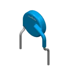
Murata DE1E3RA102MJ4BH01F — 1000 pF ±20% safety-certified radial ceramic disc capacitor, X1 440 VAC / Y1 400 VAC, E temperature characteristic, 10 mm lead spacing, through-hole.
Fix footprint and verify
Update part description
Fix footprint pads
Run verification checks
Check BOM properties
Refine this doc
Ask about this doc
Part Verification Report: DE1E3RA102MJ4BH01F
Sources reviewed
- Project name / MPN:
DE1E3RA102MJ4BH01F - Project description:
1000 pF +/-20% 400VAC Ceramic Capacitor E Radial, Disc - Official Murata datasheet/reference specification: https://search.murata.co.jp/Ceramy/image/img/A01X/G101/ENG/DE1_RA_H01F_E.pdf
Key datasheet specifications
- Manufacturer: Murata
- Series/type: DE1 / RA safety-certified ceramic disc capacitor
- Capacitance: 1000 pF
- Tolerance: ±20%
- Temperature characteristic: E
- Rated voltage: X1 440 VAC(rms), Y1 400 VAC(rms), 1500 VDC
- Operating temperature: -40 °C to +125 °C
- Body dimensions for this MPN: D = 7.0 mm, T = 4.0 mm
- Lead spacing: F = 10.0 mm
- Lead diameter: d = 0.6 mm
- Lead style: J4
- Packing quantity: 500 pcs
- Terminal count / pin count: 2
Project symbol review
- Symbol contains two terminal components with Pin Number 1 and Pin Number 2.
- Pin type is currently
Unspecifiedfor both terminals. - For a non-polarized capacitor, two generic passive terminals are acceptable; there is no polarity or functional pin naming required.
- The schematic currently shows no nets, which is acceptable for a standalone part definition.
Project footprint review
- Footprint contains two pads, but computed pad positions are approximately x=0 mm and x=0.01 mm, giving only ~0.01 mm spacing.
- Datasheet lead spacing is 10.0 mm, so the footprint pad spacing does not match the datasheet.
- Pad sizes are computed as ~0.0013 mm, far too small for 0.6 mm diameter through-hole leads.
- Pad hole type appears to fall back to default SMD rules unless overridden; this part requires through-hole pads suitable for 0.6 mm leads.
- Silkscreen/body outline appears roughly 7.0 mm x 4.0 mm in the visible drawing, consistent with the datasheet body dimensions, but the pad geometry is not consistent.
Datasheet property update
- Added the official Murata datasheet URL to both terminal components' Datasheet URL property.
Mismatches / issues flagged
- Footprint pad spacing mismatch: expected 10.0 mm, found ~0.01 mm.
- Footprint pad size mismatch: expected practical through-hole annular pads for 0.6 mm leads, found ~0.0013 mm computed size.
- Footprint pad type mismatch/risk: part is radial through-hole; pad rules appear not explicitly configured as through-hole.
- Pin descriptions are not explicit beyond pin numbers; acceptable for a non-polarized capacitor, but could be improved by setting both descriptions to
TerminalorCapacitor terminal.
Recommended fixes
- Set pad centers to 0 mm and 10.0 mm spacing, or symmetrically to -5.0 mm and +5.0 mm.
- Configure pads as plated through-hole with hole size around 0.8 mm to 0.9 mm for 0.6 mm leads, subject to fabrication tolerance preference.
- Use pad diameter around 1.6 mm to 2.0 mm for adequate annular ring.
- Keep the body/silkscreen outline at approximately 7.0 mm x 4.0 mm centered between the leads.
Sources reviewed
Key datasheet specifications
Project symbol review
Project footprint review
Datasheet property update
Mismatches / issues flagged
Recommended fixes