Project Overview and Insights
1:33
Project
Below is a detailed explanation of the project:
Purpose and Overview
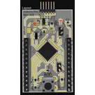
This project is an “Arduino Pro Mini 328 clone” designed as a super small and thin board capable of running an 8 MHz bootloader. Its primary purpose is to deliver the familiar Arduino functionality in a very compact form factor, making it suitable for space-constrained applications such as wearable devices, IoT sensors, or other embedded systems.
Core Components and Their Roles
| Component | Role / Function | Reference Link |
|---|---|---|
| ATMEGA328-AU (U1) | The main microcontroller (MCU) that runs the application code and provides digital and analog I/O. | ATMEGA328-AU |
| MIC5205YM5-TR (U2) | A low-dropout (LDO) linear regulator that provides a stable voltage supply to the MCU and other sensitive circuits. | MIC5205YM5-TR |
| CERAMIC RESONATOR CSTNE8M00G55A000R0 (Y1) | Supplies an 8.0MHz clock signal to the MCU ensuring stable and accurate timing for operations. | CSTNE8M00G55A000R0 |
| Decoupling and Bulk Capacitors (e.g., C1, C6, C4, C5) | Used to filter high-frequency noise and maintain voltage stability at the power pins of the MCU and regulator. | – |
| LED Indicators (LED1, LED2) | Provide visual feedback for status or error signaling in the system. | – |
| Pin Headers (J1, J2, J3, J4, J5) | Serve as connectors for programming, debugging, and interfacing with other hardware components. | – |
| Resistors | Used for tasks like biasing, pull-up/pull-down on logic signals, and current limiting for indicators. | – |
| Reset Switch (SW_Push) | A tactile switch that allows manual resetting of the MCU. | – |
Design and Implementation Steps
-
System Definition and Bootloader Choice
- The project targets an 8 MHz operational frequency. Using an 8 MHz bootloader helps in reducing power consumption and allows a smaller crystal/resonator, optimizing the board’s footprint.
-
Voltage Regulation and Power Stability
- The MIC5205YM5-TR regulator is chosen to supply a clean and stable voltage to the MCU.
- Multiple decoupling capacitors (typically 0.1 µF for high-frequency decoupling and 10 µF for bulk filtering) are placed near the power pins of both the MCU and the regulator to filter noise and minimize voltage fluctuations.
-
Clock Generation
- An 8 MHz ceramic resonator (CSTNE8M00G55A000R0) replaces a traditional crystal oscillator, offering a good balance between board size and clock stability.
-
Microcontroller and I/O Design
- The ATMEGA328-AU microcontroller (U1) is used as the central processing unit. Its design includes multiple analog and digital I/O pins.
- Connections for programming and debugging are provided through pin headers and dedicated net connections.
-
User Interface and Indication
- LED indicators (LED1 and LED2) are incorporated for system status visualization.
- A reset mechanism is included via the tactile switch (SW_Push) to allow manual restarting of the system.
-
PCB Layout Considerations
- The compact, thin board design requires careful component placement and routing. Although many copper fill errors are being reported in the current DRC review, these generally point to overlapping copper regions and can be optimized through adjustment of layout fills and trace clearances.
- Special attention is needed to resolve design rule check (DRC) errors, particularly regarding overlapping copper and floating copper areas to ensure proper manufacturability.
Functional Interactions
-
Power Management:
The MIC5205YM5-TR regulator supplies power to the ATMEGA328-AU, with decoupling capacitors ensuring a smooth voltage supply by reducing noise. -
Clock and Timing:
The resonator (Y1) generates the clock signal needed for the MCU’s timing, establishing the system’s operational frequency. -
I/O and Communication:
The ATMEGA328-AU manages all digital and analog inputs and outputs, interfacing with external sensors, actuators, or communication modules through standardized headers (J1, J2, etc.). -
User Feedback:
LEDs provide immediate visual feedback regarding the system’s state, while the reset switch enables user interaction in case of a system hang or during the programming phase.
Design Trade-offs and Optimizations
-
Frequency vs. Performance:
Running the MCU at 8 MHz reduces power consumption and simplifies the clock generation using a resonator rather than a crystal. However, it may limit processing speed compared to a 16 MHz setup. -
Board Size vs. Robustness:
The extremely small and thin design enables use in constrained spaces, though it introduces layout challenges (e.g., overlapping copper and tight routing spaces) that require careful DRC attention to ensure reliable manufacturing. -
Component Selection:
The choice of a ceramic resonator and low-dropout regulator is driven by the need for compactness and power stability. These selections strike a balance between cost, performance, and space.
Potential Challenges and Performance Considerations
-
Manufacturing DRC Issues:
The current DRC report shows overlapping copper and floating copper errors that must be addressed to prevent shorts or unreliable soldering. Refining copper fill settings and spacing may resolve these issues. -
Thermal Management:
Although power levels are low, the proximity of components on a thin board could lead to localized heating. Optimized copper pours and thermal vias would help dissipate heat more effectively if necessary. -
Signal Integrity:
Given the tight spacing and high-density routing, ensuring proper decoupling and clear separation of analog and digital signals is crucial to maintain signal integrity.
Real-World Applications and Future Enhancements
-
Applications:
This compact Arduino clone can be used in wearable devices, embedded IoT systems, remote sensors, and any application where board size and weight are critical design parameters. -
Future Enhancements:
- Layout Refinement: Revisit the PCB layout to resolve the current DRC errors, improving manufacturability and reliability.
- Expanded I/O: Consider adding extra headers or module connectors to increase interfacing flexibility.
- Alternate Voltage Options: Offer versions with different voltage regulators to support various operating conditions or reduce power consumption further.
- Enhanced Debugging: Integrate more robust onboard debugging or programming interfaces to simplify development.
Summary
In summary, the "Arduino Pro Mini 328 clone" project is a compact, efficient design that leverages a well-known microcontroller (ATMEGA328-AU) and a stable low-dropout regulator (MIC5205YM5-TR) to deliver reliable Arduino functionality in a minimal footprint. Despite the challenges related to dense layout and DRC corrections, the design choices reflect a trade-off between size, power consumption, and performance, making it an excellent candidate for a wide range of innovative embedded applications.
Adjust project description
Add project properties
Validate design constraints
377 days
Ready.
DTR
D7
D6
SCK
VCC
LED1
VCC
D8
D5
A4
D10
RESET
A1
A0
D3
MOSI
A3
MISO
A5
D2
C2
Capacitance
0.1uF
TXO
A2
RXI
D9
D4
R6
Resistance
330 Ω
R4
Resistance
500 Ω
RESET
R1
Resistance
10KΩ
R3
Resistance
10KΩ
Y1
R2
Resistance
10KΩ
Reviews

- Wirelessly connects nets on schematic. Used to organize schematics and separate functional blocks. To wirelessly connect net portals, give them same designator. #portaljharwinbarrozo43.0M
- Wirelessly connects power nets on schematic. Identical to the net portal, but with a power symbol. Used to organize schematics and separate functional blocks. To wirelessly connect power net portals, give them the same designator. #portal #powerjharwinbarrozo11.4M
- A generic fixed resistor for rapid developing circuit topology. Save precious design time by seamlessly add more information to this part (value, footprint, etc.) as it becomes available. Standard resistor values: 1.0Ω 10Ω 100Ω 1.0kΩ 10kΩ 100kΩ 1.0MΩ 1.1Ω 11Ω 110Ω 1.1kΩ 11kΩ 110kΩ 1.1MΩ 1.2Ω 12Ω 120Ω 1.2kΩ 12kΩ 120kΩ 1.2MΩ 1.3Ω 13Ω 130Ω 1.3kΩ 13kΩ 130kΩ 1.3MΩ 1.5Ω 15Ω 150Ω 1.5kΩ 15kΩ 150kΩ 1.5MΩ 1.6Ω 16Ω 160Ω 1.6kΩ 16kΩ 160kΩ 1.6MΩ 1.8Ω 18Ω 180Ω 1.8KΩ 18kΩ 180kΩ 1.8MΩ 2.0Ω 20Ω 200Ω 2.0kΩ 20kΩ 200kΩ 2.0MΩ 2.2Ω 22Ω 220Ω 2.2kΩ 22kΩ 220kΩ 2.2MΩ 2.4Ω 24Ω 240Ω 2.4kΩ 24kΩ 240kΩ 2.4MΩ 2.7Ω 27Ω 270Ω 2.7kΩ 27kΩ 270kΩ 2.7MΩ 3.0Ω 30Ω 300Ω 3.0KΩ 30KΩ 300KΩ 3.0MΩ 3.3Ω 33Ω 330Ω 3.3kΩ 33kΩ 330kΩ 3.3MΩ 3.6Ω 36Ω 360Ω 3.6kΩ 36kΩ 360kΩ 3.6MΩ 3.9Ω 39Ω 390Ω 3.9kΩ 39kΩ 390kΩ 3.9MΩ 4.3Ω 43Ω 430Ω 4.3kΩ 43KΩ 430KΩ 4.3MΩ 4.7Ω 47Ω 470Ω 4.7kΩ 47kΩ 470kΩ 4.7MΩ 5.1Ω 51Ω 510Ω 5.1kΩ 51kΩ 510kΩ 5.1MΩ 5.6Ω 56Ω 560Ω 5.6kΩ 56kΩ 560kΩ 5.6MΩ 6.2Ω 62Ω 620Ω 6.2kΩ 62KΩ 620KΩ 6.2MΩ 6.8Ω 68Ω 680Ω 6.8kΩ 68kΩ 680kΩ 6.8MΩ 7.5Ω 75Ω 750Ω 7.5kΩ 75kΩ 750kΩ 7.5MΩ 8.2Ω 82Ω 820Ω 8.2kΩ 82kΩ 820kΩ 8.2MΩ 9.1Ω 91Ω 910Ω 9.1kΩ 91kΩ 910kΩ 9.1MΩ #generics #CommonPartsLibraryjharwinbarrozo1.5M
- A generic fixed capacitor ideal for rapid circuit topology development. You can choose between polarized and non-polarized types, its symbol and the footprint will automatically adapt based on your selection. Supported options include standard SMD sizes for ceramic capacitors (e.g., 0402, 0603, 0805), SMD sizes for aluminum electrolytic capacitors, and through-hole footprints for polarized capacitors. Save precious design time by seamlessly add more information to this part (value, footprint, etc.) as it becomes available. Standard capacitor values: 1.0pF 10pF 100pF 1000pF 0.01uF 0.1uF 1.0uF 10uF 100uF 1000uF 10,000uF 1.1pF 11pF 110pF 1100pF 1.2pF 12pF 120pF 1200pF 1.3pF 13pF 130pF 1300pF 1.5pF 15pF 150pF 1500pF 0.015uF 0.15uF 1.5uF 15uF 150uF 1500uF 1.6pF 16pF 160pF 1600pF 1.8pF 18pF 180pF 1800pF 2.0pF 20pF 200pF 2000pF 2.2pF 22pF 20pF 2200pF 0.022uF 0.22uF 2.2uF 22uF 220uF 2200uF 2.4pF 24pF 240pF 2400pF 2.7pF 27pF 270pF 2700pF 3.0pF 30pF 300pF 3000pF 3.3pF 33pF 330pF 3300pF 0.033uF 0.33uF 3.3uF 33uF 330uF 3300uF 3.6pF 36pF 360pF 3600pF 3.9pF 39pF 390pF 3900pF 4.3pF 43pF 430pF 4300pF 4.7pF 47pF 470pF 4700pF 0.047uF 0.47uF 4.7uF 47uF 470uF 4700uF 5.1pF 51pF 510pF 5100pF 5.6pF 56pF 560pF 5600pF 6.2pF 62pF 620pF 6200pF 6.8pF 68pF 680pF 6800pF 0.068uF 0.68uF 6.8uF 68uF 680uF 6800uF 7.5pF 75pF 750pF 7500pF 8.2pF 82pF 820pF 8200pF 9.1pF 91pF 910pF 9100pF #generics #CommonPartsLibraryjharwinbarrozo1.5M
- A generic fixed inductor for rapid developing circuit topology. *You can now change the footprint and 3D model at the top level anytime you want. This is the power of #genericsjharwinbarrozo15.5k
- An electrical connector acting as reusable interface to a conductor and creating a point where external circuits can be connected.Terminal
- 47 kOhms ±5% 0.125W, 1/8W Chip Resistor 0805 (2012 Metric) Automotive AEC-Q200 Thick Film #forLedBlinkjharwinbarrozo1.2M
- 10uF Capacitor Aluminum Polymer 20% 16V SMD 5x5.3mm #forLedBlink #commonpartslibrary #capacitor #aluminumpolymer #radialcanjharwinbarrozo1.2M
- Yellow 595nm LED Indication - Discrete 1.7V 1206 (3216 Metric) #forLedBlinkjharwinbarrozo1.1M


Welcome 👋
Flux helps you build PCBs faster with an AI teammate!
Create your account to collaborate, stay updated, fork your own version, and get instant answers from our AI agent.