• Walkie-Talkie circuit

    Walkie-Talkie circuit

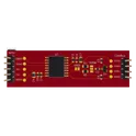
    A simple walkie-talkie circuit running off an Arduino Nano. Utilizes a BJT to amplify the microphone voltage and transmits the radio signal through a nRF24L01 series Transceiver.

    michaelkd

    2 years ago

    0 Uses

    0 Comments

    1 Star


  • GP2Y0D805Z0F Reference Design

    GP2Y0D805Z0F Reference Design

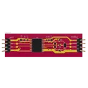
    This project is a distance detecting sensor circuit build around GP2Y0D805Z0F IC from SHARP/Socle Technology. It includes decoupling capacitors, feedback resistors, and a LED for signal indication, with power being supplied via the J1 connector. #referenceDesign #industrialsensing #sharp #template #reference-design

    +

    U

    3 years ago

    0 Uses

    0 Comments

    1 Star


  • ADM3054BRWZ-RL7 Reference Design

    ADM3054BRWZ-RL7 Reference Design

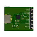
    This ADM3054BRWZ-RL7-based reference design is a CAN bus transceiver circuit, providing reliable data communication over the CAN network. The design features a range of capacitors and resistors to ensure signal integrity, and a NUP2105L for voltage protection. It's ideal for applications requiring reliable data communication in an automotive or industrial environment. #referenceDesign #project #CANbus #interface #transceiverCircuit #ADM3054 #ADM3054BRWZ-RL7 #referenceDesign #canbus #texas-instruments #template #reference-design #reference-design

    2 years ago

    0 Uses

    0 Comments

    1 Star


  • PWM Switch 2-Way

    PWM Switch 2-Way

    A circuit that uses a high/low signal to route a separate PWM signal to one of two outputs.

    3 years ago

    0 Uses

    0 Comments

    1 Star


  • Rover

    Rover

    MDD10A is the dual channel version of MD10C which is designed to drive 2 brushed DC motors with high current up to 10A continuously. Just like MD10C, the MDD10A also supports locked-antiphase and sign-magnitude PWM signal. It is also using full solid state components which result in faster response time and eliminate the wear and tear of the mechanical relay.

    3 years ago

    0 Uses

    0 Comments

    1 Star


  • ISO1042 Reference Design

    ISO1042 Reference Design

    This ISO1042BDWR-based reference design is a CAN bus transceiver circuit, providing reliable data communication over the CAN network. The design features a range of capacitors and resistors to ensure signal integrity, and a NUP2105L for voltage protection. It's ideal for applications requiring reliable data communication in an automotive or industrial environment. #referenceDesign #project #CANbus #interface #transceiverCircuit #ISO1042 #ISO1042BDWR

    3 years ago

    0 Uses

    0 Comments

    1 Star


  • Multiple Fan Board

    Multiple Fan Board

    Attach multiple fans from the output of a board that turns on and off one fan. The original fan output is used as a signal to turn a MOSFET on and off to turn on 5 fans from the same original logic. An external power supply powers all the fans.

    2 years ago

    0 Uses

    0 Comments

    1 Star


  • 100V Line Short-Circuit Detector with 1kHz Signal Injection

    100V Line Short-Circuit Detector with 1kHz Signal Injection

    This project involves designing a portable device that can inject a 1kHz sine wave signal into a 100V audio line to detect short circuits. The device should be compact (around the size of a smartphone) and include LED indicators to show the status: a green LED for normal operation and a red LED for short-circuit detection. The device will be powered either by a switching power supply or rechargeable batteries.

    +

    U

    a year ago

    0 Uses

    23 Comments

    0 Stars


  • Signal Ground gPf2

    Signal Ground gPf2

    A ground reference point from which a signal is measured.

    2 years ago

    0 Uses

    1 Comment

    0 Stars


  • 1.8T Knock Signal Conditioner 7239

    1.8T Knock Signal Conditioner 7239

    Dual-channel 1.8T knock-sensor signal conditioner powered from the MaxxECU 5 V sensor supply, producing a protected 0.5–4.5 V analog knock-severity output with RPM compensation.

    15 days ago

    0 Uses

    0 Comments

    0 Stars


  • 1.8T Knock Signal Conditioner

    1.8T Knock Signal Conditioner

    Dual-channel 1.8T knock-sensor signal conditioner powered from the MaxxECU 5 V sensor supply, producing a protected 0.5–4.5 V analog knock-severity output with RPM compensation.

    +

    U

    15 days ago

    0 Uses

    0 Comments

    0 Stars


  • Universal Inline Analog Signal Conditioner

    Universal Inline Analog Signal Conditioner

    ESP32-based universal inline analog signal conditioner with protected sensor input, DAC output, fail-safe NC relay passthrough, OLED UI, Bluetooth profile logic, and terminal-block I/O for automotive/bench use.

    4 months ago

    0 Uses

    0 Comments

    0 Stars


  • Clock Signal

    Clock Signal

    A 1 Hz clock signal generator. Simulation testing not done.

    2 years ago

    0 Uses

    0 Comments

    0 Stars


  • Dyn signal

    Dyn signal

    Welcome to your new project. Imagine what you can build here.

    3 years ago

    0 Uses

    115 Comments

    0 Stars


  • guitar signal splitter

    guitar signal splitter

    Welcome to your new project. Imagine what you can build here.

    2 years ago

    0 Uses

    13 Comments

    0 Stars


  • Signal inverter

    Signal inverter

    Welcome to your new project. Imagine what you can build here.

    2 years ago

    0 Uses

    7 Comments

    0 Stars


  • Signal Generator

    Signal Generator

    5 years ago

    0 Uses

    1 Comment

    0 Stars


  • Signal Gen Playground

    Signal Gen Playground

    5 years ago

    0 Uses

    1 Comment

    0 Stars


  • Signal Tracer

    Signal Tracer

    Modern SMD recreation of the Nuova Elettronica LX750 analog curve tracer, with analog X/Y acquisition for RP2040 processing and a 4-inch SPI TFT display interface.

    a month ago

    0 Uses

    0 Comments

    0 Stars


  • Signal Driver

    Signal Driver

    Welcome to your new project. Imagine what you can build here.

    a year ago

    0 Uses

    0 Comments

    0 Stars


  • signal jammer

    signal jammer

    Welcome to your new project. Imagine what you can build here.

    2 years ago

    0 Uses

    0 Comments

    0 Stars


  • P-001_AnandKumar_IOTSentinels

    P-001_AnandKumar_IOTSentinels

    This Gerber file contains the necessary information for fabricating the PCB design of a Bluetooth-enabled headphone. The design includes multiple layers, showcasing the electrical connections and component placements on both the top and bottom layers. Top Layer (Copper traces and components): The top copper layer is primarily responsible for routing the signals from key components such as the ESP32 module, MAX98357A audio amplifier, and the microphone. The ESP32 module, responsible for Bluetooth communication, is positioned centrally to optimize signal flow and minimize interference. Decoupling capacitors (100nF) are placed near critical components to ensure signal stability and noise suppression. Audio signal paths, as well as power distribution, are carefully routed to prevent cross-talk and ensure high-quality sound. Bottom Layer (Copper traces): The bottom layer contains the ground plane and additional routing for power and signal connections. The charging module (TP4056) and voltage regulator (AMS1117) are placed to manage power distribution, ensuring stable battery charging and regulated output for the ESP32 and other components. Connections to external interfaces such as the MicroSD breakout and auxiliary input are routed efficiently to avoid conflicts. Additional Components: All critical components are labeled, including decoupling capacitors (100nF) and resistors where needed, as well as external interfaces like the MicroSD card breakout. Mounting holes are provided for secure installation in a headphone casing, ensuring the board can be integrated seamlessly into the final product. The PCB is designed to minimize noise, with short signal paths and proper grounding for high-fidelity audio performance. This Gerber file ensures accurate manufacturing by containing data for copper layers, silkscreen, solder mask, and drill files.

    +

    U
    U
    U

    2 years ago

    0 Uses

    23 Comments

    0 Stars


  • Revolutionary Blush Gadget Copter

    Revolutionary Blush Gadget Copter

    Purpose: Design a schematic for a wearable ECG signal monitoring device that is compact and sends readings via Bluetooth. Components: Arduino Nicla Sense ME: To serve as the central processing unit of the device. MCP3911: To capture the ECG signal. AD8606: To amplify the ECG signal. Battery: To power the device with a consideration for the battery to be rechargeable via a Type-C port. Specifications: The device must be small and wearable, like the one shown in the image provided. It should have Bluetooth capabilities for transmitting data. Include a charging circuit for the battery using a Type-C connection. Enhancements: Suggest potential improvements in design for efficiency, size reduction, or additional features. Constraints: The size and shape should be as unobtrusive as possible for ease of wear. Note: Please advise on the inclusion of any additional components that may be necessary for the operation, stabilization, or improvement of signal quality.

    0 Uses

    17 Comments

    0 Stars


  • BHI160B Reference design

    BHI160B Reference design

    This project is a reference design for the BHI160B sensor featuring an I2C interface with QWIIC and pin headers. The design includes decoupling capacitors and pull-up resistors for signal integrity. It's powered by a 3.3V supply. #referenceDesign #project #sensor #accelerometer #BHI160B #referenceDesign #imu #stm #template #reference-design

    +

    U

    3 years ago

    0 Uses

    15 Comments

    0 Stars


  • Yearling Sapphire Dejarik

    Yearling Sapphire Dejarik

    Purpose: Design a schematic for a wearable ECG signal monitoring device that is compact and sends readings via Bluetooth. Components: Arduino Nicla Sense ME: To serve as the central processing unit of the device. MCP3911: To capture the ECG signal. AD8606: To amplify the ECG signal. Battery: To power the device with a consideration for the battery to be rechargeable via a Type-C port. Specifications: The device must be small and wearable, like the one shown in the image provided. It should have Bluetooth capabilities for transmitting data. Include a charging circuit for the battery using a Type-C connection. Enhancements: Suggest potential improvements in design for efficiency, size reduction, or additional features. Constraints: The size and shape should be as unobtrusive as possible for ease of wear. Note: Please advise on the inclusion of any additional components that may be necessary for the operation, stabilization, or improvement of signal quality.

    0 Uses

    14 Comments

    0 Stars


Previous

Page 2 of 7

Next