Chat
Welcome to Flux
Treat Flux like your intern. Tell it what you'd like to build and it'll get to work. You can also ask it questions, brainstorm ideas, and teach it your preferences. Learn More
Explain project
Write a project description
Find schematic issues
Create a test plan
Simulate a circuit
Prepare for Manufacturing
Component Selection Workflow
New Subsystem Wizard
Write I2C initialization code
Generate firmware skeleton
U2
@copilot, develop an FMEA (Failure Mode and Effects Analysis) report in a table ...

@copilot, develop an FMEA (Failure Mode and Effects Analysis) report in a table format that analyzes the systems schematic, each unique component specification, and operational parameters. It should identify critical failure modes, assess their impact, and recommend mitigation actions based on severity, occurrence probability, and detectability. Include columns such as: process step, potential failure mode, potential failure effect, S, O, D, RPN, Action Recommended, and any other you see fit.
1y
Creating an FMEA report involves several steps. Given the project description and components of your WiFi Camera with Motion Detection design, I'll draft a basic FMEA table for you.
FMEA Table
Table
| Process Step | Potential Failure Mode | Potential Failure Effect | Severity (S) | Occurrence (O) | Detectability (D) | Risk Priority Number (RPN) | Action Recommended |
|---|---|---|---|---|---|---|---|
| Power Supply (+5V, +3V3) | Voltage regulator failure | System power loss | 9 | 6 | 4 | 216 | Use voltage regulators with overcurrent and thermal protection |
| ESP32-CAM | Communication failure | Loss of image/data transmission | 8 | 5 | 3 | 120 | Implement robust error-handling and retry logic |
| HC-SR501 | False trigger or no detection | Erratic camera activation | 7 | 4 | 3 | 84 | Calibrate PIR sensor; add filtering in software |
| Transistor Q1 (S8050) | Short circuit or open circuit | Inability to control current | 7 | 4 | 4 | 112 | Add current limiting resistors; consider a different transistor |
| Resistor R3 (1k) | Increased resistance | Reduced current flow | 5 | 3 | 5 | 75 | Use precision resistors with low temperature coefficients |
| Resistor R4 (10k) | Decreased resistance | Excessive current flow | 6 | 3 | 5 | 90 | Inspect and select quality-controlled resistors |
| Connector J1/J2 | Poor connection | Intermittent functionality | 8 | 4 | 4 | 128 | Ensure proper connector assembly and use locking connectors |
| Net Connections | Signal loss or noise | Degraded performance | 7 | 3 | 3 | 63 | Use shielding and maintain good routing practices |
- Severity (S): Rating from 1 to 10 based on the impact of the failure mode (1 being least severe, 10 being most severe).
- Occurrence (O): Rating from 1 to 10 based on the probability of failure occurrence (1 being least likely, 10 being most likely).
- Detectability (D): Rating from 1 to 10 based on the ease of detecting the failure (1 being easily detectable, 10 being difficult to detect).
- Risk Priority Number (RPN): Calculated as $RPN = S \times O \times D$. This number helps prioritize which failure modes to address first.
- Action Recommended: Suggestions for mitigating or preventing this failure mode.
This FMEA table serves as a preliminary analysis. Let me know if you have specific parameters that need adjusting or if there's anything else you'd like to add!
1y
3
create a detailed step by step plan table for ESP32-CAM1 to verify its functiona...
1y
Here's a detailed step-by-step plan in a table format to verify the functionality of the ESP32-CAM1 module:
Table
| Step | Description | Expected Result |
|---|---|---|
| 1 | Power Supply Verification | Ensure the module is supplied with 5V and 3.3V power as required. |
| 2 | Check Connections | Verify connections for GND (common ground) and VCC to avoid any loose or incorrect connections. |
| 3 | Flash Test Firmware | Flash a test firmware using an appropriate IDE (Arduino IDE or ESP-IDF) and USB-TTL converter. |
| 4 | Open Serial Monitor | Open the serial monitor to check and confirm the module's boot log and any debug messages. |
| 5 | Configure WiFi Settings | In the test firmware, configure and input the SSID and password for your Wi-Fi network. |
| 6 | Upload Code | Upload the code and check for any upload errors. The module should boot up with the firmware. |
| 7 | Scan for WiFi Access Points | Allow the module to scan and print available WiFi access points to verify WiFi functionality. |
| 8 | Connect to WiFi Network | Connect the ESP32-CAM to the preset WiFi network and check for successful connection via serial monitor. |
| 9 | Ping Test | Ping an external server (such as google.com) to verify connectivity and response time. |
| 10 | Capture Camera Feed | Access camera feed using the IP address shown in the serial monitor in a web browser. It should display a video stream. |
| 11 | Verify Camera Quality | Observe the camera feed and verify the image quality and resolution settings. |
| 12 | Validate Additional Pin Functions | Test additional GPIO pins using simple LED blink or I/O operations to ensure they function correctly. |
| 13 | Test Reset Functionality | Press the reset button on the module and observe the reboot sequence for any errors or issues. |
| 14 | Check for Heat and Stability | Observe the module for any overheating or stability issues during extended use. |
This systematic plan should help in thoroughly verifying the functionality of the ESP32-CAM module, leading to successful integration into a project. Let me know if you have any questions or need further assistance!
1y
1
+5V
ESP_RX
+3V3
+5V
C1
Capacitance
Capacitance
BOOT
R3
Resistance
1kΩ
ESP_TX
+5V
R4
Resistance
10kΩ
BOOT
+3V3
+3V3
J1
Q1
ESP32-CAM1
ESP_RX
ESP_TX
+5V
+5V
J2
No files yet
Reviews
Documents
Documents are markdown text files which describe project goals, capture details, or even simulation outputs.
Assets

WiFi Camera with Motion Detection-removebg-preview.png
WiFi Camera with Motion Detection-removebg-previewThumbnailWiFi Camera with Motion Detection Reference Design
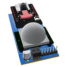
This project is a WiFi Camera with Motion Detection, utilizing ESP32-CAM module and HC-SR501 PIR sensor. The camera is activated by the sensor's output. The system also includes power regulation and communication headers for setup and control.
#WiFi #MCU #PIR #ReferenceDesign #project #ESP32 #camera #referenceDesign #edgeComputing #espressif #template #reference-design
Properties
Pricing & Availability
Distributor | Qty 1 |
|---|---|
Digi-Key | $0.01–$36.00 |
LCSC | $0.00–$0.03 |
Verical | $0.01–$0.01 |
Controls
Welcome 👋
Flux helps you build PCBs faster with an AI teammate!
Create your account to collaborate, stay updated, fork your own version, and get instant answers from our AI agent.
qwertuzu
copilot