Datasheet Review and Validation
Thought for 7 mins 28 sec
Here is a complete execution of your 4 requested steps for the Adam Tech DB25-PT-1-SL-JS part project.
Step 1 — Review of available part information
- MPN: DB25-PT-1-SL-JS
- Manufacturer: Adam Tech
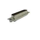
- Description: D-Sub Standard Connectors 25P MALE STRAIGHT PCB MOUNT
- Mount: Standard
- Designator prefix: J
- Datasheet property: Present (Datasheet URL set)
- Schematic symbol composition: 27 terminals total — 25 signal pins and 2 mounting/jackscrew holes (1 … 13; 14 … 25; MH1, MH2)
- Footprint assets: Found (KiCad module embedded; 3D model reference present)
- Library search link for part name: DB25-PT-1-SL-JS
Step 2 — Datasheet check and update
- A datasheet URL is already set on this part: https://app.adam-tech.com/products/download/data_sheet/198648/dxxx-pt-1-sl-js-data-sheet.pdf
- No update needed.
Step 3 — Datasheet scan and metadata extraction
The Adam Tech-hosted PDF could not be parsed reliably, so I additionally consulted two manufacturer-series PDFs (mirrors/hosted by Mouser and BDTIC) that include the ordering key, mechanical drawings, and electrical specifications for the DB/DA/DE D‑Sub series including PT (Plug, straight PCB tails) with JS/SL options:
- Series datasheet (Adam Tech, hosted by Mouser): https://www.mouser.com/datasheet/2/4/AdamTech_010824_DA_DE_DP_Series-3395758.pdf
- Series datasheet (Adam Tech, hosted by BDTIC): https://www.bdtic.com/datasheet/ADAM-TECH/D-Subminiatures.pdf
Datasheet-derived summary (series covering DB25-PT-1-…)
- Ordering key highlights
- PT = Plug, straight PCB tail (vertical/THT)
- ST = Socket, straight PCB tail
- 1 = Standard tail length for 0.062–0.125 inch PCBs (E ≈ 0.189 in / 4.80 mm)
- SL = Bottom-side riveted #4-40 clinch nuts
- JS = Top-side riveted #4-40 jackscrews
- JSl = Bottom-side clinch nuts with jackscrews installed
- Pin count and style
- Positions: 25
- Rows: 2 (staggered)
- Gender: Plug (male)
- Key mechanical dimensions for DB25 plug, straight PCB tail (typical series values)
- Column pitch: 2.770 mm (0.109 in)
- Row spacing: 2.840 mm (0.112 in)
- Mounting hole drill: 3.05 mm (0.120 in), two places
- Example overall dimension references for DB25 (series tables)
- A = 38.96 mm (1.534 in)
- B = 47.04 mm (1.852 in) — mounting-hole center spacing
- C = 53.04 mm (2.088 in)
- Recommended PCB drill for signal pins: 1.00 mm (0.039 in)
- Electrical characteristics (Adam Tech D‑Sub series)
- Operating voltage: 250 V AC/DC max
- Current rating: 5 A max (per contact)
- Contact resistance: 20 mΩ max (initial)
- Insulation resistance: 5000 MΩ min
- Dielectric withstanding voltage: 1000 VAC for 1 minute
- Operating temperature: The series documentation contains two variants:
- −65 °C to +125 °C (Mouser-hosted PDF)
- −55 °C to +105 °C (BDTIC-hosted PDF)
- Materials and plating
- Contacts: Phosphor bronze
- Contact plating: Gold flash (15 µin and 30 µin options), over nickel underplate overall
- Shell: Steel, tin or zinc plated
- Noted features/options
- Clinch nuts/jackscrews mounting options
- High-temp insulator option (HT)
- EMI filtered options on some variants (EMI)
Step 4 — Cross-check of symbol and footprint vs datasheet
What matches the datasheet
- Symbol pin count and numbering:
- Footprint pad count and geometry:
- 27 holes defined: 25 signal pads + 2 mounting holes.
- Top-row pad centers at y = 0 mm; bottom-row at y ≈ 2.84 mm; x-pitch = 2.77 mm; bottom row offset by ≈ 1.385 mm — matches series drawings.
- Mounting-hole centers at x = −6.900 mm and x = 40.140 mm, y = 1.42 mm; the center spacing is 47.04 mm, matching the datasheet B dimension for DB25.
- Mounting-hole drills at 3.05 mm align with series drawings for #4-40 jackscrew/clinch-nut hardware.
- Pin 1 marker present in silk.
Potential issues to flag
- Signal-pin drill diameter vs datasheet recommendation
- Footprint uses 1.10 mm drill for signal pads; series drawings typically call out ø1.00 mm (0.039 in).
- Impact: A 0.10 mm oversize drill can reduce annular ring or solder fillet for the same pad OD and may slightly loosen press fit of tails (these are solder tails, not press-fit pins). It is often acceptable, but it deviates from the recommended hole size. Consider changing drills to ø1.00 mm if you want to follow the series recommendation exactly.
- Mounting-hole plating
- Mounting holes (3.05 mm) are currently defined as standard plated through holes in the embedded KiCad module. For #4-40 jackscrews/clinch-nut clearances, these holes are typically NPTH (non-plated) mechanical holes.
- Risk: Plating in a jackscrew clearance/mechanical hole can be damaged by hardware or cause unintended grounding paths through the shell hardware. Recommend converting MH1/MH2 to NPTH with 3.05 mm drill and an appropriate keepout annulus on copper/mask.
- Temperature range discrepancy between series documents
- Mouser-hosted series PDF states −65 °C to +125 °C, while the BDTIC-hosted series PDF states −55 °C to +105 °C. The specific variant (PT/SL/JS options and plating thickness) may drive the exact rating. If environmental rating is critical for your product, confirm with the manufacturer or the specific, per-part PDF for DB25-PT-1-SL-JS.
Footprint details found in project
- Module name: DB25PT1SLJS (KiCad-style footprint embedded)
- Signal pads: 1–13 at y=0, 14–25 at y=2.84, 2.77 mm pitch; 1.65 mm pad OD with 1.10 mm drill
- Mounting holes: 3.05 mm drill at x = −6.900 mm and x = 40.140 mm
- 3D model reference: DB25-PT-1-SL-JS.stp
Recommendations
- Change mounting holes MH1/MH2 to NPTH with 3.05 mm drill.
- Consider reducing signal drill from 1.10 mm to 1.00 mm to align with series recommended hole size (check your fab’s min annular ring and tolerance if keeping 1.10 mm).
- If your BOM or product documentation must state environmental limits, reconcile the temperature range by confirming with Adam Tech or a per-part datasheet page that explicitly names DB25-PT-1-SL-JS.
References used for extraction
- Adam Tech series datasheet (Mouser mirror): https://www.mouser.com/datasheet/2/4/AdamTech_010824_DA_DE_DP_Series-3395758.pdf
- Adam Tech series datasheet (BDTIC mirror): https://www.bdtic.com/datasheet/ADAM-TECH/D-Subminiatures.pdf
- Project’s existing datasheet URL: https://app.adam-tech.com/products/download/data_sheet/198648/dxxx-pt-1-sl-js-data-sheet.pdf
If you want, I can apply the mounting-hole NPTH change and adjust the signal drill size.
Run full DRC/ERC
Check pad drills vs datasheet
Verify MPN in BOM
Pull official Adam Tech PDF