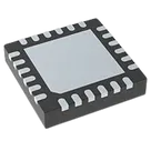
Part Project Review Checklist
Thought for 2 mins 10 sec
Part Review Summary
1) Available Project Information
2) Datasheet Status
3) Datasheet Metadata Extraction
Device Overview and Special Features
Ordering / Package Metadata
Absolute Maximum Ratings
Recommended Operating Conditions
Key Electrical Characteristics
Pin Descriptions
Package Dimensions and Land Pattern
4) Symbol / Footprint Cross-Check
Cross-Check Findings
Pin-Type Metadata Mismatches
Bottom Line
Recommended Fixes
Table
| Field | Value |
|---|---|
| Project / part | This part project is for LM25117PSQE/NOPB |
| Manufacturer | Texas Instruments |
| MPN | LM25117PSQE/NOPB |
| Designator prefix | U |
| Datasheet URL present in project | Yes - PDF |
| Package in project footprint | QFN50P400X400X80-25N |
| Footprint source asset | QFN50P400X400X80-25N.kicad_mod |
| 3D model present | Yes - STEP model is attached |
| Schematic pin count | 24 terminals |
| Footprint pad count in asset | 25 pads total, including exposed pad 25 |
| Project description | LM25117PSQE/NOPB RTW24_2P6X2P6_TEX RTW24_2P6X2P6_TEX-M RTW24_2P6X2P6_TEX-L |
Table
| Check | Result |
|---|---|
| Datasheet already set? | Yes |
| Web search needed? | No |
| Property update needed? | No |
Table
| Category | Summary |
|---|---|
| Function | Synchronous buck controller for high-voltage / wide-input step-down regulators |
| Control method | Emulated peak current mode control |
| Input operating range | 4.5 V to 42 V |
| Frequency range | Programmable from 50 kHz to 750 kHz |
| Output programming | Programmable output from 0.8 V reference |
| Gate drive | External high-side and low-side NMOS gate drivers, adaptive dead-time control |
| Notable features | Diode emulation mode, analog current monitor, programmable current limit, hiccup overcurrent protection, soft-start/tracking, programmable UVLO, thermal shutdown |
| Internal bias behavior | Internal high-voltage bias regulator, with optional switchover to external bias supply |
Table
| Item | Datasheet Value |
|---|---|
| Exact orderable | LM25117PSQE/NOPB |
| Package family | WQFN (RTW) |
| Pin count | 24 pins |
| Body size | 4.00 mm x 4.00 mm |
| Max package height | 0.8 mm max |
| MSL | Level-1-260C-UNLIM |
| Part marking | L25117P |
Table
| Parameter | Min | Max | Unit |
|---|---|---|---|
| VIN to AGND | -0.3 | 45 | V |
| SW to AGND | -3.0 | 45 | V |
| HB to SW | -0.3 | 15 | V |
| VCC to AGND | -0.3 | 15 | V |
| HO to SW | -0.3 | HB + 0.3 | V |
| LO to AGND | -0.3 | VCC + 0.3 | V |
| FB, DEMB, RES, VCCDIS, UVLO to AGND | -0.3 | 15 | V |
| CM, COMP to AGND | -0.3 | 7 | V |
| SS, RAMP, RT to AGND | -0.3 | 7 | V |
| CS, CSG, PGND to AGND | -0.3 | 0.3 | V |
| Storage temperature | -55 | 150 | °C |
| Junction temperature | -40 | 150 | °C |
Table
| Parameter | Min | Max | Unit |
|---|---|---|---|
| VIN | 4.5 | 42 | V |
| VCC | 4.5 | 14 | V |
| HB to SW | 4.5 | 14 | V |
| Junction temperature | -40 | 125 | °C |
Table
| Category | Parameter | Min | Typ | Max | Unit |
|---|---|---|---|---|---|
| VIN supply | Operating current | - | 4.8 | 6.2 | mA |
| VIN supply | Shutdown current | - | 16 | 40 | µA |
| VCC regulator | Regulation | 6.85 | 7.6 | 8.2 | V |
| VCC regulator | Sourcing current limit | - | 30 | 42 | mA |
| VCC UVLO | Rising threshold | 3.75 | 4.0 | 4.15 | V |
| VCCDIS | Rising threshold | 1.22 | 1.25 | 1.29 | V |
| UVLO | Rising threshold | 1.22 | 1.25 | 1.29 | V |
| Soft-start | SS current source | 7 | 10 | 12 | µA |
| Feedback | FB reference voltage | 788 | 800 | 812 | mV |
| Error amp | DC gain | - | 80 | - | dB |
| Error amp | Unity gain bandwidth | - | 3 | - | MHz |
| Oscillator | RT = 25 kOhm | 180 | 200 | 220 | kHz |
| Oscillator | RT = 10 kOhm | 430 | 480 | 530 | kHz |
| Current limit | Sense threshold | 106 | 120 | 135 | mV |
| HO driver | Peak source current | - | 2.2 | - | A |
| HO driver | Peak sink current | - | 3.3 | - | A |
| LO driver | Peak source current | - | 2.5 | - | A |
| LO driver | Peak sink current | - | 3.3 | - | A |
| Thermal | Shutdown | - | 165 | - | °C |
Table
| WQFN Pin | Name | Datasheet Type | Datasheet Description |
|---|---|---|---|
| 1 | DEMB | Input | Enables diode emulation when low; internal 50 kOhm pull-down |
| 2 | RES | Output | Restart timer for hiccup mode using external capacitor |
| 3 | SS | Input | Soft-start ramp capacitor input with internal 10 µA source |
| 4 | RT | Input | Oscillator programming / sync input |
| 5 | AGND | Ground | Analog ground |
| 6 | NC | NC | No electrical contact |
| 7 | VCCDIS | Input | Disables internal VCC regulator when above 1.25 V |
| 8 | FB | Input | Feedback input, regulation threshold 0.8 V |
| 9 | COMP | Output | Error amplifier output |
| 10 | CM | Output | Average sensed inductor current monitor |
| 11 | RAMP | Input | PWM ramp signal input |
| 12 | CS | Input | Current sense input, high side of sense resistor |
| 13 | CSG | Input | Kelvin ground sense to current sense resistor |
| 14 | PGND | Ground | Power ground return for low-side gate driver |
| 15 | LO | Output | Low-side NMOS gate drive |
| 16 | VCC | Power / Output / Input | Bias supply pin, decouple locally to PGND |
| 17 | NC | NC | No electrical contact |
| 18 | SW | Input / Output | Switching node |
| 19 | HO | Output | High-side NMOS gate drive |
| 20 | HB | Power | Bootstrap supply |
| 21 | NC | NC | No electrical contact |
| 22 | VIN | Power / Input | Supply input for VCC regulator |
| 23 | NC | NC | No electrical contact |
| 24 | UVLO | Input | Undervoltage lockout programming pin |
| 25 | EP | Exposed pad | Electrically isolated; should be soldered to ground plane for thermal performance |
Table
| Item | Datasheet Value |
|---|---|
| Package code | RTW0024A |
| Package type | WQFN |
| Package size A | 4.1 / 3.9 mm |
| Package size B | 4.1 / 3.9 mm |
| Lead pitch | 0.5 mm |
| Lead width | 0.3 / 0.2 mm |
| Lead length | 0.5 / 0.3 mm |
| Exposed pad | 2.6 mm +/- 0.1 mm square |
| Board-layout terminal pad example | 24x (0.25 mm x 0.6 mm) |
| Pad clearance around body | 0.07 mm min / 0.07 mm max all around |
| Stencil guidance | 78% printed solder coverage on exposed pad |
| Mask style | Non-solder-mask-defined preferred |
Table
| Area | Result | Risk | Details |
|---|---|---|---|
| MPN vs package | Pass | Low | Project MPN and datasheet orderable both match LM25117PSQE/NOPB, which is the 24-pin RTW WQFN version. |
| Symbol pin count vs datasheet | Pass | Low | Symbol has 24 terminals, matching the package pin count. |
| Footprint package family | Pass | Low | Footprint asset name indicates 4.0 mm x 4.0 mm, 0.5 mm pitch, 25-pad QFN, consistent with datasheet package family. |
| Exposed pad presence | Partial pass | Medium | Footprint asset includes pad 25 at 2.6 mm x 2.6 mm, matching datasheet EP size. |
| Exposed pad in symbol | Needs review | Medium | The symbol exposes only 24 terminals and does not include an EP terminal. Since the datasheet says EP is electrically isolated, that is electrically acceptable, but the package note still requires it to be soldered for thermal/mechanical performance. |
| Exposed pad soldering guidance | Concern | High | Datasheet says EP should be soldered to the ground plane and is critical for thermal/mechanical performance. If this footprint instance does not preserve pad 25 and its paste/mask correctly in manufacturing output, assembly reliability can suffer. |
| Perimeter pad size | Deviation | Medium | Datasheet example land pattern is 0.25 mm x 0.6 mm. Imported footprint pads appear to be about 0.27 mm x 0.86 mm. That is noticeably longer than TI's example and should be verified against the intended IPC or source-library footprint. |
| EP stencil coverage | Mismatch | High | Datasheet calls for 78% solder coverage under EP. The footprint asset appears to define a single paste opening about 1.64 mm x 1.64 mm, which is only about 39.8% of EP area. That is a significant mismatch. |
| Pin naming consistency | Pass | Low | Symbol terminal names line up with datasheet names and pin numbers. |
| Pin type metadata | Mismatch | Low to Medium | Several pin electrical types in the symbol metadata do not match datasheet function. This usually will not break manufacturing, but can weaken ERC quality and part correctness. |
| No-connect pins | Pass | Low | NC pins are present in symbol and footprint positions consistent with datasheet. |
Table
| Pin | Datasheet Role | Current Project Role | Impact |
|---|---|---|---|
| VIN, pin 22 | Power / Input | Input | ERC quality issue |
| UVLO, pin 24 | Input | Unspecified | ERC quality issue |
| RES, pin 2 | Output | Unspecified | ERC quality issue |
| HB, pin 20 | Power | Unspecified | ERC quality issue |
| SW, pin 18 | Input / Output | Unspecified | ERC quality issue |
| CSG, pin 13 | Input | Unspecified | ERC quality issue |
| AGND, pin 5 | Ground | Power In | ERC semantics issue |
| PGND, pin 14 | Ground | Power In | ERC semantics issue |
| VCC, pin 16 | Power / Output / Input | Power In | Slight semantic mismatch |
| RAMP, pin 11 | Input | Unspecified | ERC quality issue |
Table
| Severity | Finding |
|---|---|
| High | The exposed-pad stencil definition appears inconsistent with the datasheet's 78% paste recommendation. |
| High | The thermal / mechanical exposed-pad implementation must be verified in final manufacturing outputs. |
| Medium | The perimeter copper pad size deviates from TI's example board layout and should be confirmed against the intended footprint source. |
| Low / Medium | Several symbol pin types should be corrected to improve rule checking and part accuracy. |
Table
| Priority | Action |
|---|---|
| 1 | Verify that exposed pad 25 is truly present in the generated footprint/manufacturing outputs and not lost due to missing symbol mapping. |
| 2 | Adjust the exposed-pad paste pattern to match TI's stencil guidance much more closely. |
| 3 | Recheck perimeter pad dimensions against TI's RTW example land pattern or the exact source-library recommendation used to generate this footprint. |
| 4 | Correct symbol electrical pin types for VIN, UVLO, RES, HB, SW, CSG, AGND, PGND, VCC, and RAMP. |
If you want, I can turn this into a clean pass/fail checklist file for this part project.
Make checklist file
Inspect exposed pad
Review pin metadata