Pin Function Grouping

2:38
Considering skill datasheets.
Looking for "pin definitions pin layout ESP32-WROOM-32UE pin number pin name function" in C701346.pdf?spm=wm.sxq.inf.ggs___wm.ssy.bg.0.xh&lcsc_vid=T1kIXgFeT1NaU1RXQFBbUlUHT1cKU1NXFVBeX1VSTlAxVlNRQFheUFNRR1hXUTsOAxUeFF5JWBYZEEoKFBINSQcJGk4dAgUUFAk%3D
Looking for "Table ESP32-WROOM-32UE pin definitions GND 3V3 EN SENSOR_VP SENSOR_VN IO0 IO2 IO4 IO5 IO12 IO13 IO14 IO15 IO16 IO17 IO18 IO19 IO21 IO22 IO23 IO25 IO26 IO27 IO32 IO33 IO34 IO35 RXD0 TXD0" in C701346.pdf?spm=wm.sxq.inf.ggs___wm.ssy.bg.0.xh&lcsc_vid=T1kIXgFeT1NaU1RXQFBbUlUHT1cKU1NXFVBeX1VSTlAxVlNRQFheUFNRR1hXUTsOAxUeFF5JWBYZEEoKFBINSQcJGk4dAgUUFAk%3D
Looking for "ESP32-WROOM-32UE Pin Definitions Type Function Power Ground Analog GPIO UART SPI I2C JTAG strapping pins" in C701346.pdf?spm=wm.sxq.inf.ggs___wm.ssy.bg.0.xh&lcsc_vid=T1kIXgFeT1NaU1RXQFBbUlUHT1cKU1NXFVBeX1VSTlAxVlNRQFheUFNRR1hXUTsOAxUeFF5JWBYZEEoKFBINSQcJGk4dAgUUFAk%3D
Searching web for: "ESP32-WROOM-32UE datasheet pin definitions pin numbers 38 pins"
Found 1 results.
Fetching web page.
Found 1 results.
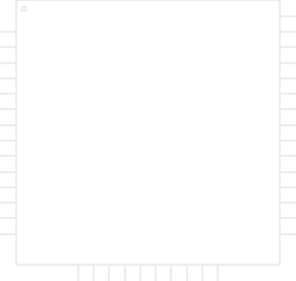
Recommended Primary Pin Groups
| Group | Pins | Why grouped here |
|---|---|---|
| Power | 2: 3V3 | Main 3.3 V module supply input |
| Ground | 1: GND, 15: GND, 38: GND | Ground / return pins |
| Control / Enable | 3: EN | Chip enable / shutdown control; should not be left floating |
| Analog Input Only | 4: SENSOR_VP, 5: SENSOR_VN, 6: IO34, 7: IO35 | Input-only GPIO/ADC-capable pins |
| RTC / ADC / Touch GPIO | 8: IO32, 9: IO33, 10: IO25, 11: IO26, 12: IO27, 13: IO14, 14: IO12, 16: IO13, 23: IO15, 24: IO2, 25: IO0, 26: IO4 | General GPIO pins with ADC/RTC/touch functions; also include several boot/strapping-capable pins |
| Digital GPIO / UART / SPI / EMAC | 27: IO16, 28: IO17, 29: IO5, 30: IO18, 31: IO19, 33: IO21, 34: RXD0, 35: TXD0, 36: IO22, 37: IO23 | General digital I/O pins with UART/SPI/EMAC alternate functions |
| No Connect | 17: NC, 18: NC, 19: NC, 20: NC, 21: NC, 22: NC, 32: NC | Pins marked NC / not for user connection in the module pin table |
Pin-by-Pin Assignment
| Pin No. | Pin Name | Primary Group | Datasheet functions / notes |
|---|---|---|---|
| 1 | GND | Ground | Ground |
| 2 | 3V3 | Power | Power supply |
| 3 | EN | Control / Enable | High: on; low: off; do not leave floating |
| 4 | SENSOR_VP | Analog Input Only | GPIO36, ADC1_CH0, RTC_GPIO0 |
| 5 | SENSOR_VN | Analog Input Only | GPIO39, ADC1_CH3, RTC_GPIO3 |
| 6 | IO34 | Analog Input Only | GPIO34, ADC1_CH6, RTC_GPIO4; input-only |
| 7 | IO35 | Analog Input Only | GPIO35, ADC1_CH7, RTC_GPIO5; input-only |
| 8 | IO32 | RTC / ADC / Touch GPIO | GPIO32, XTAL_32K_P, ADC1_CH4, TOUCH9, RTC_GPIO9 |
| 9 | IO33 | RTC / ADC / Touch GPIO | GPIO33, XTAL_32K_N, ADC1_CH5, TOUCH8, RTC_GPIO8 |
| 10 | IO25 | RTC / ADC / Touch GPIO | GPIO25, DAC_1, ADC2_CH8, RTC_GPIO6, EMAC_RXD0 |
| 11 | IO26 | RTC / ADC / Touch GPIO | GPIO26, DAC_2, ADC2_CH9, RTC_GPIO7, EMAC_RXD1 |
| 12 | IO27 | RTC / ADC / Touch GPIO | GPIO27, ADC2_CH7, TOUCH7, RTC_GPIO17, EMAC_RX_DV |
| 13 | IO14 | RTC / ADC / Touch GPIO | GPIO14, ADC2_CH6, TOUCH6, RTC_GPIO16, MTMS, HSPICLK, HS2_CLK, SD_CLK, EMAC_TXD2 |
| 14 | IO12 | RTC / ADC / Touch GPIO | GPIO12, ADC2_CH5, TOUCH5, RTC_GPIO15, MTDI, HSPIQ, HS2_DATA2, SD_DATA2, EMAC_TXD3 |
| 15 | GND | Ground | Ground |
| 16 | IO13 | RTC / ADC / Touch GPIO | GPIO13, ADC2_CH4, TOUCH4, RTC_GPIO14, MTCK, HSPID, HS2_DATA3, SD_DATA3, EMAC_RX_ER |
| 17 | NC | No Connect | GPIO6–GPIO11 are connected to onboard SPI flash and are not led out |
| 18 | NC | No Connect | GPIO6–GPIO11 are connected to onboard SPI flash and are not led out |
| 19 | NC | No Connect | GPIO6–GPIO11 are connected to onboard SPI flash and are not led out |
| 20 | NC | No Connect | GPIO6–GPIO11 are connected to onboard SPI flash and are not led out |
| 21 | NC | No Connect | GPIO6–GPIO11 are connected to onboard SPI flash and are not led out |
| 22 | NC | No Connect | GPIO6–GPIO11 are connected to onboard SPI flash and are not led out |
| 23 | IO15 | RTC / ADC / Touch GPIO | GPIO15, ADC2_CH3, TOUCH3, MTDO, HSPICS0, RTC_GPIO13, HS2_CMD, SD_CMD, EMAC_RXD3 |
| 24 | IO2 | RTC / ADC / Touch GPIO | GPIO2, ADC2_CH2, TOUCH2, RTC_GPIO12, HSPIWP, HS2_DATA0, SD_DATA0 |
| 25 | IO0 | RTC / ADC / Touch GPIO | GPIO0, ADC2_CH1, TOUCH1, RTC_GPIO11, CLK_OUT1, EMAC_TX_CLK |
| 26 | IO4 | RTC / ADC / Touch GPIO | GPIO4, ADC2_CH0, TOUCH0, RTC_GPIO10, HSPIHD, HS2_DATA1, SD_DATA1, EMAC_TX_ER |
| 27 | IO16 | Digital GPIO / UART / SPI / EMAC | GPIO16, HS1_DATA4, U2RXD, EMAC_CLK_OUT |
| 28 | IO17 | Digital GPIO / UART / SPI / EMAC | GPIO17, HS1_DATA5, U2TXD, EMAC_CLK_OUT_180 |
| 29 | IO5 | Digital GPIO / UART / SPI / EMAC | GPIO5, VSPICS0, HS1_DATA6, EMAC_RX_CLK |
| 30 | IO18 | Digital GPIO / UART / SPI / EMAC | GPIO18, VSPICLK, HS1_DATA7 |
| 31 | IO19 | Digital GPIO / UART / SPI / EMAC | GPIO19, VSPIQ, U0CTS, EMAC_TXD0 |
| 32 | NC | No Connect | NC |
| 33 | IO21 | Digital GPIO / UART / SPI / EMAC | GPIO21, VSPIHD, EMAC_TX_EN |
| 34 | RXD0 | Digital GPIO / UART / SPI / EMAC | GPIO3, U0RXD, CLK_OUT2 |
| 35 | TXD0 | Digital GPIO / UART / SPI / EMAC | GPIO1, U0TXD, CLK_OUT3, EMAC_RXD2 |
| 36 | IO22 | Digital GPIO / UART / SPI / EMAC | GPIO22, VSPIWP, U0RTS, EMAC_TXD1 |
| 37 | IO23 | Digital GPIO / UART / SPI / EMAC | GPIO23, VSPID, HS1_STROBE |
| 38 | GND | Ground | Ground |
- I intentionally did not duplicate pins across groups, even when a pin has multiple alternate functions.
- If you want Flux
Pin Groupproperties instead of broader symbol sections, a practical mapping would be:Power,Ground,Control,ADC1_InputOnly,RTC_ADC_TOUCH_GPIO,Digital_Comm_GPIO, andNC. - If you want sub-symbol blocks for the schematic symbol, use the same group names above;
Powershould include both 3V3 and all GND pins.

Welcome 👋
Flux accelerates your PCB design with AI.
Create your account to start using this component and bring your ideas to life.