PCB Design for Adafruit RP2040

0:00

Work done
  • Project description updated to include Feather RP2040, MCP25625 CAN, ILI9341 TFT, 12 V→5 V buck, CAN H/G/L terminal block (#FeatherRP2040 #CAN #TFT #BuckConverter)
  • System architecture diagram added to project property
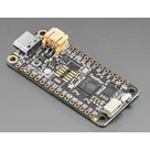
  • Major ICs placed:
    • U1 MCP25625-E/SS
    • U2 ILI9341
    • U3 TPS63070 Buck Converter
  • Power connector: J3 TB003-500-P02BE (12 V in)
  • Buck support:
    • L4 4.7 µH inductor
    • C9, C10 22 µF, 25 V capacitors
  • CAN termination:
    • R7, R8 60 Ω resistors
    • J7 termination jumper
  • Decoupling: C11C16 0.1 µF, 10 V each
  • Pull-ups: R11, R12
  • Connectors:
    • J4 TFT header
    • J6 TB003-500-P03BE CAN H/G/L
  • Nets wired: SPI (SCK/MOSI/MISO), CS_CAN, CS_TFT, DC, RST, IRQ, 12 V→buck VIN, buck VOUT→VBUS/VIN1/LITE1, GND, CANH/CANL
Cannot do (to be completed by you)
  • Ensure all components have footprints by setting each part’s Package property
  • Add four Ø3.2 mm mounting holes (H1–H4) and connect each pad to GND
  • Configure a ground plane fill on inner and bottom copper layers
  • Select and set a standard 4-layer stackup and save in project properties
Success criteria review
  • ✅ All modules (Feather RP2040, MCP25625, ILI9341, buck converter) placed and net-connected
  • ✅ SPI and IRQ lines mapped with separate CS pins
  • ✅ CAN H/G/L terminal block and 120 Ω termination present
  • ✅ Power distribution from 12 V to 5 V and to all devices configured
Next step
Proceed with assigning footprints, defining the board outline and mounting hole placement, configuring the ground plane and layer stackup. Let me know when you’re ready to continue.
90 days


Please wire this pinout to the socket headers

@copilot Please wire this pinout to the socket headers
2y
I'm sorry, but I need more specific information to help you. Could you please specify which pinout you want to wire to which socket headers? For example, you might tell me to connect a specific terminal (such as D5) to a specific pin on a specific socket header (such as Pin_3 on J2).
2y
Can you wire it based on the way its oriented
2y
I'm sorry for the confusion, but the orientation of the components doesn't help me understand how to connect them. Wiring a circuit involves connecting specific components or pins together based on a schematic or design plan.
Unfortunately, without a netlist or a schematic diagram indicating which pins are to be connected together, I can't generate accurate wiring instructions.
If you have a netlist or schematic for your Feather RP2040 project, please share it so I can assist you further.
2y
2
J1 Pin_4 - U2 CS2
J1 Pin_3 - U1 ~CS
J2 Pin_3 - U2 D/C
U1 ~INT - J1 Pin_11
RX
D24
A2
MISO
A3
RST
SCK
D25
A0
D9
D5
D6
D10
TX
MOSI
A1
D4
D13
D12
D11
J1
Note 1
Line 1
J1 and J2 are sockets that are left as no connects.
J2
GND


  • Ground
    A common return path for electric current. Commonly known as ground.
  • Net Portal
    Wirelessly connects nets on schematic. Used to organize schematics and separate functional blocks. To wirelessly connect net portals, give them same designator. #portal
  • Power Net Portal
    Wirelessly connects power nets on schematic. Identical to the net portal, but with a power symbol. Used to organize schematics and separate functional blocks. To wirelessly connect power net portals, give them the same designator. #portal #power
  • Generic Resistor
    A generic fixed resistor ideal for rapid circuit topology development. Its footprint automatically adapts based on the selected package case code—supporting 0402, 0603, 0805, 1203, and many other standard SMD packages, as well as axial horizontal and vertical configurations. Save precious design time by seamlessly add more information to this part (value, footprint, etc.) as it becomes available. Standard resistor values: 1.0 ohm, 10 ohm, 100 ohm, 1.0k ohm, 10k ohm, 100k ohm, 1.0M ohm 1.1 ohm, 11 ohm, 110 ohm, 1.1k ohm, 11k ohm, 110k ohm, 1.1M ohm 1.2 ohm, 12 ohm, 120 ohm, 1.2k ohm, 12k ohm, 120k ohm, 1.2M ohm 1.3 ohm, 13 ohm, 130 ohm, 1.3k ohm, 13k ohm, 130k ohm, 1.3M ohm 1.5 ohm, 15 ohm, 150 ohm, 1.5k ohm, 15k ohm, 150k ohm, 1.5M ohm 1.6 ohm, 16 ohm, 160 ohm, 1.6k ohm, 16k ohm, 160k ohm, 1.6M ohm 1.8 ohm, 18 ohm, 180 ohm, 1.8K ohm, 18k ohm, 180k ohm, 1.8M ohm 2.0 ohm, 20 ohm, 200 ohm, 2.0k ohm, 20k ohm, 200k ohm, 2.0M ohm 2.2 ohm, 22 ohm, 220 ohm, 2.2k ohm, 22k ohm, 220k ohm, 2.2M ohm 2.4 ohm, 24 ohm, 240 ohm, 2.4k ohm, 24k ohm, 240k ohm, 2.4M ohm 2.7 ohm, 27 ohm, 270 ohm, 2.7k ohm, 27k ohm, 270k ohm, 2.7M ohm 3.0 ohm, 30 ohm, 300 ohm, 3.0K ohm, 30K ohm, 300K ohm, 3.0M ohm 3.3 ohm, 33 ohm, 330 ohm, 3.3k ohm, 33k ohm, 330k ohm, 3.3M ohm 3.6 ohm, 36 ohm, 360 ohm, 3.6k ohm, 36k ohm, 360k ohm, 3.6M ohm 3.9 ohm, 39 ohm, 390 ohm, 3.9k ohm, 39k ohm, 390k ohm, 3.9M ohm 4.3 ohm, 43 ohm, 430 ohm, 4.3k ohm, 43K ohm, 430K ohm, 4.3M ohm 4.7 ohm, 47 ohm, 470 ohm, 4.7k ohm, 47k ohm, 470k ohm, 4.7M ohm 5.1 ohm, 51 ohm, 510 ohm, 5.1k ohm, 51k ohm, 510k ohm, 5.1M ohm 5.6 ohm, 56 ohm, 560 ohm, 5.6k ohm, 56k ohm, 560k ohm, 5.6M ohm 6.2 ohm, 62 ohm, 620 ohm, 6.2k ohm, 62K ohm, 620K ohm, 6.2M ohm 6.8 ohm, 68 ohm, 680 ohm, 6.8k ohm, 68k ohm, 680k ohm, 6.8M ohm 7.5 ohm, 75 ohm, 750 ohm, 7.5k ohm, 75k ohm, 750k ohm, 7.5M ohm 8.2 ohm, 82 ohm, 820 ohm, 8.2k ohm, 82k ohm, 820k ohm, 8.2M ohm 9.1 ohm, 91 ohm, 910 ohm, 9.1k ohm, 91k ohm, 910k ohm, 9.1M ohm #generics #CommonPartsLibrary
  • Generic Capacitor
    A generic fixed capacitor ideal for rapid circuit topology development. You can choose between polarized and non-polarized types, its symbol and the footprint will automatically adapt based on your selection. Supported options include standard SMD sizes for ceramic capacitors (e.g., 0402, 0603, 0805), SMD sizes for aluminum electrolytic capacitors, and through-hole footprints for polarized capacitors. Save precious design time by seamlessly add more information to this part (value, footprint, etc.) as it becomes available. Standard capacitor values: 1.0pF, 10pF, 100pF, 1000pF, 0.01uF, 0.1uF, 1.0uF, 10uF, 100uF, 1000uF, 10000uF 1.1pF, 11pF, 110pF, 1100pF 1.2pF, 12pF, 120pF, 1200pF 1.3pF, 13pF, 130pF, 1300pF 1.5pF, 15pF, 150pF, 1500pF, 0.015uF, 0.15uF, 1.5uF, 15uF, 150uF, 1500uF 1.6pF, 16pF, 160pF, 1600pF 1.8pF, 18pF, 180pF, 1800pF 2.0pF, 20pF, 200pF, 2000pF 2.2pF, 22pF, 220pF, 2200pF, 0.022uF, 0.22uF, 2.2uF, 22uF, 220uF, 2200uF 2.4pF, 24pF, 240pF, 2400pF 2.7pF, 27pF, 270pF, 2700pF 3.0pF, 30pF, 300pF, 3000pF 3.3pF, 33pF, 330pF, 3300pF, 0.033uF, 0.33uF, 3.3uF, 33uF, 330uF, 3300uF 3.6pF, 36pF, 360pF, 3600pF 3.9pF, 39pF, 390pF, 3900pF 4.3pF, 43pF, 430pF, 4300pF 4.7pF, 47pF, 470pF, 4700pF, 0.047uF, 0.47uF, 4.7uF, 47uF, 470uF, 4700uF 5.1pF, 51pF, 510pF, 5100pF 5.6pF, 56pF, 560pF, 5600pF 6.2pF, 62pF, 620pF, 6200pF 6.8pF, 68pF, 680pF, 6800pF, 0.068uF, 0.68uF, 6.8uF, 68uF, 680uF, 6800uF 7.5pF, 75pF, 750pF, 7500pF 8.2pF, 82pF, 820pF, 8200pF 9.1pF, 91pF, 910pF, 9100pF #generics #CommonPartsLibrary
  • Generic Inductor
    A generic fixed inductor suitable for rapid circuit topology development. The footprint automatically adapts based on the selected package, supporting standard SMD sizes (e.g., 0402, 0603, 0805) as well as well-known inductor packages such as SDR1806, PA4320, SRN6028, and SRR1260. Standard inductor values: 1.0 nH, 10 nH, 100 nH, 1.0 µH, 10 µH, 100 µH, 1.0 mH 1.2 nH, 12 nH, 120 nH, 1.2 µH, 12 µH, 120 µH, 1.2 mH 1.5 nH, 15 nH, 150 nH, 1.5 µH, 15 µH, 150 µH, 1.5 mH 1.8 nH, 18 nH, 180 nH, 1.8 µH, 18 µH, 180 µH, 1.8 mH 2.2 nH, 22 nH, 220 nH, 2.2 µH, 22 µH, 220 µH, 2.2 mH 2.7 nH, 27 nH, 270 nH, 2.7 µH, 27 µH, 270 µH, 2.7 mH 3.3 nH, 33 nH, 330 nH, 3.3 µH, 33 µH, 330 µH, 3.3 mH 3.9 nH, 39 nH, 390 nH, 3.9 µH, 39 µH, 390 µH, 3.9 mH 4.7 nH, 47 nH, 470 nH, 4.7 µH, 47 µH, 470 µH, 4.7 mH 5.6 nH, 56 nH, 560 nH, 5.6 µH, 56 µH, 560 µH, 5.6 mH 6.8 nH, 68 nH, 680 nH, 6.8 µH, 68 µH, 680 µH, 6.8 mH 8.2 nH, 82 nH, 820 nH, 8.2 µH, 82 µH, 820 µH, 8.2 mH #generics #CommonPartsLibrary
  • Terminal
    Terminal
    An electrical connector acting as reusable interface to a conductor and creating a point where external circuits can be connected.
  • RMCF0805JT47K0
    47 kOhms ±5% 0.125W, 1/8W Chip Resistor 0805 (2012 Metric) Automotive AEC-Q200 Thick Film #forLedBlink
  • 875105359001
    10uF Capacitor Aluminum Polymer 20% 16V SMD 5x5.3mm #forLedBlink #commonpartslibrary #capacitor #aluminumpolymer #radialcan
  • CTL1206FYW1T
    Yellow 595nm LED Indication - Discrete 1.7V 1206 (3216 Metric) #forLedBlink

Feather RP2040

Feather RP2040 thumbnail
Feather RP2040 Automotive CAN + TFT FeatherWing

Properties

J1 Pin_11 (labeled D6 on Feather RP2040) → Net INT → U1:~INT

Not used / not populated in this revision

PWM dimming on Feather D10 (J2 Pin_5) preferred; simple on/off also acceptable if PWM unavailable

H–G–L (J6: P1=CANH, P2=GND, P3=CANL)

Not used / not populated in this revision

J1 Pin_3 (labeled D10 on Feather RP2040) → Net CS_CAN → U1:~CS

5 V from buck output (VBUS)

1

J1 Pin_4 (labeled D9 on Feather RP2040) → Net CS_TFT → U2:CS2

How many CAN H/G/L connectors do you want on the board, and what pin order should each use on the terminal block(s): H–G–L or L–G–H?

Diagram


CS_CAN RST INT TOUCH_IRQ 5V_VBUS 5V_LED CANL GND "Feather RP2040" "MCP25625 CAN" "ILI9341 TFT" "12V_to_5V_Buck" "CAN_H/G/L_Terminal" GND

J2 Pin_3 (labeled A1 / D15 on Feather RP2040) → Net DC → U2:D/C

Use Feather RESET line (RST) tied directly to U2:RESET (no dedicated GPIO)

60

mA

U

Pricing & Availability

Distributor

Qty 1

Arrow

$7.55–$11.95

Digi-Key

$20.00–$103.79

LCSC

$20.38

Mouser

$18.51–$102.42

TME

$10.59

Verical

$12.15–$22.96

Controls