Pin Labeling Verification
Thought for 46 sec
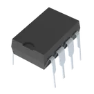
In many Flux schematic symbols for dual op amps like the NE5534P, the outputs aren’t shown as one of the eight physical pins listed in the datasheet. Instead, the symbol typically separates the functional blocks so that the output nodes appear as distinct terminals on the schematic symbol.
For example, even though the datasheet lists only the following eight physical pins:
Table
| Pin Number | Function |
|---|---|
| 1 | Offset Null (Op-Amp 1) |
| 2 | Inverting Input (Op-Amp 1) |
| 3 | Non-Inverting Input (Op-Amp 1) |
| 4 | Negative Supply (V−) |
| 5 | Non-Inverting Input (Op-Amp 2) |
| 6 | Inverting Input (Op-Amp 2) |
| 7 | Offset Null (Op-Amp 2) |
| 8 | Positive Supply (V+) |
the schematic symbol in Flux will usually add separate output nodes for each op amp channel. For the first amplifier, the output node is typically drawn adjacent to the op amp symbol (often labeled “OUT” or similar) and is internally connected to the amplifier’s output circuitry. The second amplifier does the same.
If you’re having trouble locating them:
- Zoom in on the symbol: Look for a node or pad that isn’t one of the eight numbered pins.
- Check the symbol legend: Sometimes the output node is labeled with a different identifier (like "OP1 Out" or simply "OUT").
- Compare with a typical application diagram: The NE5534 datasheet application diagram shows the op amp’s outputs as separate from the offset null and input pins.
Let me know if you’d like any more guidance on identifying or updating these nodes in your Flux schematic!
Confirm output labels
Clarify node naming
Verify output connection