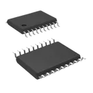
Using MCP2515 on Board
Thought for 3 mins 4 sec
Great question. Here’s how to integrate the MCP2515-I/ST on your board, step by step.
- Power and decoupling
- Tie VDD to your logic rail and VSS to ground. Datasheet: “Supply Voltage 2.7 V to 5.5 V.”
- Place a 100nF Capacitor and a 1uF Capacitor close to VDD–VSS. Per best practice, ensure capacitors “operate at no more than 60% of their maximum rated voltage.”
- Clock (crystal or external clock)
- If using a crystal, connect it between OSC1 and OSC2 with load capacitors as per the crystal spec and datasheet. Datasheet: “designed to operate with a crystal or ceramic resonator connected to the OSC1 and OSC2 pins… requires the use of a parallel cut crystal.”
- Example tested values (datasheet): “4 MHz: C1=27 pF, C2=27 pF; 8 MHz: C1=22 pF, C2=22 pF; 20 MHz: C1=15 pF, C2=15 pF.”
- You can also drive OSC1 from an external clock if preferred.
- MCU SPI interface and interrupt
- Connect MCU SPI to SCK, SI, SO, and chip select ~CS. Datasheet: “High-Speed SPI Interface (10 MHz): SPI modes 0,0 and 1,1… CS must be held low while any operation is performed.”
- Route ~INT to an MCU interrupt-capable GPIO.
- For signal integrity on fast edges, add 22–33 Ω series resistors near the MCU on SCK/MOSI per best practice: use 33Ω Resistor.
- Reset pin
- Pull ~RESET up to VDD with a 10kΩ Resistor. Optionally add an RC for power-on reset.
- Datasheet: “It is highly recommended that the RESET command be sent (or the RESET pin be lowered) as part of the power-on initialization sequence… device is held in Reset for a minimum of 2 µs after VDD reaches the operating voltage (tRL).”
- CAN physical layer (requires a transceiver)
- Connect TXCAN and RXCAN to a CAN transceiver (logic-level compatible with your VDD), then from the transceiver to CANH/CANL. Datasheet shows the “Example System Implementation” with an external transceiver.
- Typical 3.3 V transceiver: SN65HVD230. Typical 5 V transceiver: MCP2551.
- Terminate the CAN bus with a 120Ω Resistor at each end. Best practice: “include 120Ω termination resistors.”
- Optional/other pins
- CLKOUT/SOF: optional clock out or Start-of-Frame indicator; leave unconnected if unused.
- ~TX0RTS, ~TX1RTS, ~TX2RTS: configurable Request-to-Send inputs or general inputs; leave as inputs if not used. Datasheet: “The TXnRTS pins are input pins that can be configured as… Request-to-Send inputs… or standard digital inputs.”
- ~RX0BF, ~RX1BF: optional buffer-full/interrupt outputs; tie to MCU GPIOs if you want per-buffer interrupts, otherwise leave unconnected.
Quick placement/layout notes
- Keep decoupling close to VDD–VSS.
- Short, symmetric crystal routing at OSC1/OSC2.
- Short SPI traces; add series damping (22–33 Ω) as above.
- Place the CAN transceiver near the connector that goes to the harness; keep the CANH/CANL pair tightly coupled and routed as a differential pair.
Do you plan to run the MCP2515 at 3.3 V or 5 V, and which MCU are you using? If you want, I can add the MCP2515, a matching CAN transceiver, crystal, and basic passives to your project and wire the essentials—just say the word.
Set voltage and MCU
Differential pair rule
RC time constant
Find LDO regulator