Net Portal Pin Specifications

The Net Portal is not an active electronic component but a schematic object used exclusively to represent a net connection across different parts of your design. As such, it does not have a datasheet, nor does it include electrical specifications or inherent input/output characteristics.
Below is what you need to know about the Net Portal (in this case, the one labeled IO12):

Table


AttributeDescription
FunctionActs as a marker to indicate that all instances of the same net (by name or designator) are electrically connected across the schematic.
Pin(s)It typically has a single pin, P1, which is used to tie together different wires or connections on the schematic.
Input/Output CharacteristicsThe Net Portal does not drive or receive signals. It has no active circuitry, buffering, or loading. It is purely a connectivity symbol.
Special Considerations- It is used solely for organizing net connectivity in the schematic.- It is not included in the BOM or PCB layout.- Ensure consistent naming across your design to maintain proper connectivity.
Since the Net Portal is a schematic utility symbol rather than an actual circuit device, there is no datasheet available. Let me know if you’d like information on other parts or further clarification on schematic connectivity in Flux.
Explain net portals
IO16
USBDP
BOOT
ESP_EN
IO4
IO16
IO2
ESP_RX
IO12
IO12
ESP_TX
CC2
USBDN
IO12
IO4
ESP_EN
IO14
USBDN
USBDP
BOOT
CC1
IO13
USBDN
IO2
ESP_EN
IO15
ESP_EN
IO15
BOOT
CC1
IO15
USBDP
ESP_TX
BOOT
IO13
ESP_RX
USBDP
USBDP
IO16
IO14
ESP_RX
ESP_RX
USBDN
ESP_TX
IO2
ESP_TX
CC2
IO14
IO13
IO4
ESP_EN
USBDN
D1
+3V3
IO2
+3V3
VBUS
+5V
ESP_EN
VBUS
IO13
+5V
IO12
+5V
ESP_RX
IO4
+5V
+3V3
+5V
+3V3
GND
IO15
+3V3
+3V3
+3V3
+3V3
+3V3
+5V
GND
+3V3
IO14
ESP_TX
BOOT
IO16
R5
Resistance
0 Ω
R2
Resistance
1kΩ
R1
Resistance
Resistance
Resistance
5.1kΩ
R4
Resistance
0 Ω
R3
Resistance
Resistance
Resistance
5.1kΩ
D2
IC1
D4
C2
Capacitance
10uF
RST
C6
Capacitance
0.1uF
D3
C7
Capacitance
0.1uF
C3
Capacitance
10uF
C4
Capacitance
10uF
U1
J3
J5
J4
ESP32-CAM1
LED1
C5
Capacitance
10uF

No files yet

Documents

    Documents are markdown text files which describe project goals, capture details, or even simulation outputs.

    Assets

    ESP-CAM Motherboard Module-removebg-preview.png

    ESP-CAM Motherboard Module-removebg-preview.png

    ESP-CAM Motherboard Module-removebg-previewThumbnail

    ESP-CAM Motherboard Module 7rcj

    ESP-CAM Motherboard Module 7rcj thumbnail
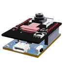
    This project is a motherboard for the ESP32-CAM module, which enables easy and flexible WiFi camera applications. The motherboard provides power supply, programming interface, and GPIO expansion for the ESP32-CAM. It also supports external sensors for more functionality. #motherboard #WiFi #MCU #ReferenceDesign #project #ESP32 #camera #reusable #module #edgeComputing #espressif #template

    Pricing & Availability

    Distributor

    Qty 1

    Arrow

    $0.05–$0.27

    Digi-Key

    $1.11–$2.40

    LCSC

    $1.49–$2.08

    Mouser

    $1.12

    Verical

    $0.33–$0.55

    Controls