Part Information Review and Update
6:49
Running design review.
Reviewing the bill of materials.
Analyzing the PCB layout.
Analyzing the schematic.
Analyzing uploaded files.
Searching the project.
Analyzing the PCB layout.
Searching for project components.
Searching 5 domains.
Exploring symbol arrangement.
Searching 3 domains.
Summarizing project details.
Search complete — 103 results across 4 domains.
Searching the project.
Running multiple web searches.
Searching 3 domains.
Found 1 results.
Found 1 results.
Search complete — 18 results across 2 domains.
Fetching web page.
Looking for "For Samtec TSW-105-07-G-S, extract the meaning of each code field in the part number, pin count, row count, pitch, termination type, plating, and any key electrical/mechanical specs." in tsw-sxx.pdf
Found 1 results.
Looking for "For Samtec TSW-105-07-G-S, extract the exact mechanical dimensions, recommended PCB hole/drill information, post tail length, overall body dimensions, and pin numbering orientation for the 5-position single-row variant." in tsw-xxx-xx-xxx-x-xx-xxx-mkt.pdf
Searching the project (2 questions).
Searching for assets.
Searching 2 domains.
Searching for components.
Searching 3 domains.
Searching for PCB details.
Searching 2 domains.
Verifying component data.
Searching 2 domains.
Searching for project details.
Searching 3 domains.
Checking footprint details.
Searching fetch_url.
Looking for "TSW-105-07-G-S recommended PCB layout pad pitch drill hole pad size shape row count pin 1 orientation or single row 5 positions" in tsw-sxx.pdf
Clarifying the search strategy.
Searching 2 domains.
Searching fetch_url.
Looking for "TSW-105-07-G-S footprint recommended PCB layout drill hole pad size pad shape row count pin 1 orientation print" in tsw_th.pdf
Searching the project.
Searching for assets.
Searching 2 domains.
Searching pcb.
Investigating file content.
Searching 2 domains.
Fetching footprint details.
Searching fetch_url.
Looking for "TSW-105-07-G-S pitch drill recommended PCB layout hole size pad size row count pin 1 orientation single row .100" in tsw-sxx.pdf
Evaluating project data limitations.
Searching for footprint details.
Searching fetch_url.
Looking for "TSW-105-07-G-S PCB layout hole size 5 positions single row recommended footprint pin 1" in ?TSW
Searching for pad specifics.
Searching assets.
Exploring pad geometry.
Searching pcb.
Searching for footprint details.
Searching chat.
Exploring component details.
Clarifying pin orientation.
Search complete — 113 results across 4 domains.
Searching the project.
Searching for components.
Searching 3 domains.
Clarifying search findings.
Search complete — 21 results across 2 domains.
- Added the project Datasheet property as the official Samtec series spec PDF:
https://suddendocs.samtec.com/productspecs/tsw-sxx.pdfafter confirming the project review flagged Datasheet as missing and web search identified that Samtec-hosted PDF as the correct official source for this series.
Project metadata
| Field | Current value |
|---|---|
| Manufacturer | Samtec |
| MPN | TSW-105-07-G-S |
| Designator Prefix | J |
| Description | Connector Header Through Hole 5 position 0.100" (2.54 mm), SWD header 1x5 2.54 mm |
| Datasheet | Now set to official Samtec series PDF |
Pin Numberset to 01-05Pin Typeset to Passive- vertical single-column symbol placement, ordered top-to-bottom 01, 02, 03, 04, 05
- a KiCad footprint asset:
SAMTEC_TSW-105-07-G-S.kicad_mod - a STEP model:
TSW-105-07-G-S.step - five footprint pads: 01-05
- single-row, 5-position footprint structure
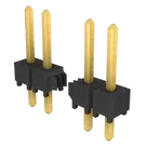
- Series: TSW
- Type: terminal strip / classic PCB header
- Pitch: 2.54 mm (0.100")
- Contact system: 0.64 mm (0.025") square post
- Variant decode:
105= 5 positions07= lead style -07G= gold platingS= single row
- Orientation / mount style: vertical through-hole
- Packaging: bulk
- Current rating: 4.7 A per powered pin per row
- Voltage rating: 465 VAC
- Operating temperature:
- -55 C to +125 C for gold-plated versions
- Mechanical drawing data confirms:
- 5 positions
- 1 row
- 2.54 mm pitch
- straight-post version
- pin 1 at one end of the row
Matches
| Item | Project | Datasheet | Result |
|---|---|---|---|
| MPN | TSW-105-07-G-S | TSW-105-07-G-S family decode matches exact variant | Match |
| Manufacturer | Samtec | Samtec | Match |
| Pin count | 5 terminals / 5 pads | 105 = 5 positions | Match |
| Row count | Single row | S = single row | Match |
| Pitch | Implied by SWD header description / indexed footprint | 2.54 mm | Match |
| Mount style | Description says through-hole | TSW is vertical through-hole for this variant | Match |
| Symbol ordering | 01 to 05 in a single vertical column | Single-row numbering is consistent with a 1x5 header | Match |
| Footprint pad count | 5 pads | 5-position part | Match |
Issues / mismatches / gaps
| Area | Finding | Severity |
|---|---|---|
| Datasheet property | Was missing; now fixed | Resolved |
| Pin descriptions | No pin names or descriptions are present on 01, 02, 03, 04, 05 | Warning |
| Symbol metadata | No pin group, section, or orientation metadata beyond pin number/type/position | Warning |
| Footprint geometry verification | Indexed project data confirms 5 pads and 2.54 mm pitch, but does not expose full raw pad geometry, so I could not directly verify copper pad size/shape or drill definition from the stored footprint file itself | Partial verification only |
| Package property | I did not find a dedicated package/property field populated for the part | Warning |
| Review inconsistency | The review engine still reports project Part Type missing, even though project context shows Part Type: Connector | Needs recheck |
- correct manufacturer/MPN
- correct 1x5, 2.54 mm, through-hole, single-row header structure
- symbol and footprint both reflect 5 pins
- missing descriptive pin metadata
- incomplete package/footprint-verification detail from the indexed asset view
- review inconsistency around the project
Part Type
Ready.
Reviews

- Wirelessly connects nets on schematic. Used to organize schematics and separate functional blocks. To wirelessly connect net portals, give them same designator. #portaljharwinbarrozo43.0M
- Wirelessly connects power nets on schematic. Identical to the net portal, but with a power symbol. Used to organize schematics and separate functional blocks. To wirelessly connect power net portals, give them the same designator. #portal #powerjharwinbarrozo11.4M
- A generic fixed resistor ideal for rapid circuit topology development. Its footprint automatically adapts based on the selected package case code—supporting 0402, 0603, 0805, 1203, and many other standard SMD packages, as well as axial horizontal and vertical configurations. Save precious design time by seamlessly add more information to this part (value, footprint, etc.) as it becomes available. Standard resistor values: 1.0 ohm, 10 ohm, 100 ohm, 1.0k ohm, 10k ohm, 100k ohm, 1.0M ohm 1.1 ohm, 11 ohm, 110 ohm, 1.1k ohm, 11k ohm, 110k ohm, 1.1M ohm 1.2 ohm, 12 ohm, 120 ohm, 1.2k ohm, 12k ohm, 120k ohm, 1.2M ohm 1.3 ohm, 13 ohm, 130 ohm, 1.3k ohm, 13k ohm, 130k ohm, 1.3M ohm 1.5 ohm, 15 ohm, 150 ohm, 1.5k ohm, 15k ohm, 150k ohm, 1.5M ohm 1.6 ohm, 16 ohm, 160 ohm, 1.6k ohm, 16k ohm, 160k ohm, 1.6M ohm 1.8 ohm, 18 ohm, 180 ohm, 1.8K ohm, 18k ohm, 180k ohm, 1.8M ohm 2.0 ohm, 20 ohm, 200 ohm, 2.0k ohm, 20k ohm, 200k ohm, 2.0M ohm 2.2 ohm, 22 ohm, 220 ohm, 2.2k ohm, 22k ohm, 220k ohm, 2.2M ohm 2.4 ohm, 24 ohm, 240 ohm, 2.4k ohm, 24k ohm, 240k ohm, 2.4M ohm 2.7 ohm, 27 ohm, 270 ohm, 2.7k ohm, 27k ohm, 270k ohm, 2.7M ohm 3.0 ohm, 30 ohm, 300 ohm, 3.0K ohm, 30K ohm, 300K ohm, 3.0M ohm 3.3 ohm, 33 ohm, 330 ohm, 3.3k ohm, 33k ohm, 330k ohm, 3.3M ohm 3.6 ohm, 36 ohm, 360 ohm, 3.6k ohm, 36k ohm, 360k ohm, 3.6M ohm 3.9 ohm, 39 ohm, 390 ohm, 3.9k ohm, 39k ohm, 390k ohm, 3.9M ohm 4.3 ohm, 43 ohm, 430 ohm, 4.3k ohm, 43K ohm, 430K ohm, 4.3M ohm 4.7 ohm, 47 ohm, 470 ohm, 4.7k ohm, 47k ohm, 470k ohm, 4.7M ohm 5.1 ohm, 51 ohm, 510 ohm, 5.1k ohm, 51k ohm, 510k ohm, 5.1M ohm 5.6 ohm, 56 ohm, 560 ohm, 5.6k ohm, 56k ohm, 560k ohm, 5.6M ohm 6.2 ohm, 62 ohm, 620 ohm, 6.2k ohm, 62K ohm, 620K ohm, 6.2M ohm 6.8 ohm, 68 ohm, 680 ohm, 6.8k ohm, 68k ohm, 680k ohm, 6.8M ohm 7.5 ohm, 75 ohm, 750 ohm, 7.5k ohm, 75k ohm, 750k ohm, 7.5M ohm 8.2 ohm, 82 ohm, 820 ohm, 8.2k ohm, 82k ohm, 820k ohm, 8.2M ohm 9.1 ohm, 91 ohm, 910 ohm, 9.1k ohm, 91k ohm, 910k ohm, 9.1M ohm #generics #CommonPartsLibraryjharwinbarrozo1.5M
- A generic fixed capacitor ideal for rapid circuit topology development. You can choose between polarized and non-polarized types, its symbol and the footprint will automatically adapt based on your selection. Supported options include standard SMD sizes for ceramic capacitors (e.g., 0402, 0603, 0805), SMD sizes for aluminum electrolytic capacitors, and through-hole footprints for polarized capacitors. Save precious design time by seamlessly add more information to this part (value, footprint, etc.) as it becomes available. Standard capacitor values: 1.0pF, 10pF, 100pF, 1000pF, 0.01uF, 0.1uF, 1.0uF, 10uF, 100uF, 1000uF, 10000uF 1.1pF, 11pF, 110pF, 1100pF 1.2pF, 12pF, 120pF, 1200pF 1.3pF, 13pF, 130pF, 1300pF 1.5pF, 15pF, 150pF, 1500pF, 0.015uF, 0.15uF, 1.5uF, 15uF, 150uF, 1500uF 1.6pF, 16pF, 160pF, 1600pF 1.8pF, 18pF, 180pF, 1800pF 2.0pF, 20pF, 200pF, 2000pF 2.2pF, 22pF, 220pF, 2200pF, 0.022uF, 0.22uF, 2.2uF, 22uF, 220uF, 2200uF 2.4pF, 24pF, 240pF, 2400pF 2.7pF, 27pF, 270pF, 2700pF 3.0pF, 30pF, 300pF, 3000pF 3.3pF, 33pF, 330pF, 3300pF, 0.033uF, 0.33uF, 3.3uF, 33uF, 330uF, 3300uF 3.6pF, 36pF, 360pF, 3600pF 3.9pF, 39pF, 390pF, 3900pF 4.3pF, 43pF, 430pF, 4300pF 4.7pF, 47pF, 470pF, 4700pF, 0.047uF, 0.47uF, 4.7uF, 47uF, 470uF, 4700uF 5.1pF, 51pF, 510pF, 5100pF 5.6pF, 56pF, 560pF, 5600pF 6.2pF, 62pF, 620pF, 6200pF 6.8pF, 68pF, 680pF, 6800pF, 0.068uF, 0.68uF, 6.8uF, 68uF, 680uF, 6800uF 7.5pF, 75pF, 750pF, 7500pF 8.2pF, 82pF, 820pF, 8200pF 9.1pF, 91pF, 910pF, 9100pF #generics #CommonPartsLibraryjharwinbarrozo1.5M
- A generic fixed inductor suitable for rapid circuit topology development. The footprint automatically adapts based on the selected package, supporting standard SMD sizes (e.g., 0402, 0603, 0805) as well as well-known inductor packages such as SDR1806, PA4320, SRN6028, and SRR1260. Standard inductor values: 1.0 nH, 10 nH, 100 nH, 1.0 µH, 10 µH, 100 µH, 1.0 mH 1.2 nH, 12 nH, 120 nH, 1.2 µH, 12 µH, 120 µH, 1.2 mH 1.5 nH, 15 nH, 150 nH, 1.5 µH, 15 µH, 150 µH, 1.5 mH 1.8 nH, 18 nH, 180 nH, 1.8 µH, 18 µH, 180 µH, 1.8 mH 2.2 nH, 22 nH, 220 nH, 2.2 µH, 22 µH, 220 µH, 2.2 mH 2.7 nH, 27 nH, 270 nH, 2.7 µH, 27 µH, 270 µH, 2.7 mH 3.3 nH, 33 nH, 330 nH, 3.3 µH, 33 µH, 330 µH, 3.3 mH 3.9 nH, 39 nH, 390 nH, 3.9 µH, 39 µH, 390 µH, 3.9 mH 4.7 nH, 47 nH, 470 nH, 4.7 µH, 47 µH, 470 µH, 4.7 mH 5.6 nH, 56 nH, 560 nH, 5.6 µH, 56 µH, 560 µH, 5.6 mH 6.8 nH, 68 nH, 680 nH, 6.8 µH, 68 µH, 680 µH, 6.8 mH 8.2 nH, 82 nH, 820 nH, 8.2 µH, 82 µH, 820 µH, 8.2 mH #generics #CommonPartsLibraryjharwinbarrozo15.7k
- An electrical connector acting as reusable interface to a conductor and creating a point where external circuits can be connected.Terminal
- 47 kOhms ±5% 0.125W, 1/8W Chip Resistor 0805 (2012 Metric) Automotive AEC-Q200 Thick Film #forLedBlinkjharwinbarrozo1.2M
- 10uF Capacitor Aluminum Polymer 20% 16V SMD 5x5.3mm #forLedBlink #commonpartslibrary #capacitor #aluminumpolymer #radialcanjharwinbarrozo1.2M
- Yellow 595nm LED Indication - Discrete 1.7V 1206 (3216 Metric) #forLedBlinkjharwinbarrozo1.1M


TSW-105-07-G-S
Properties
Pricing & Availability
See prices from popular manufacturers for your project.
Controls
Welcome 👋
Flux accelerates your PCB design with AI.
Create your account to start using this component and bring your ideas to life.