Part Information Review and Verification
2:39
Read TPS259814ARPWR datasheet for recommended operating conditions input v.
Read TPS259814ARPWR datasheet for thermal information package R-PW HTSSOP .
Read TPS259814ARPWR datasheet for features description 2.7 V to 16 V 10 A .
Read schematic.
Read layout.
Thought for a moment
Thought for a moment
Thought for a moment
Thought for a moment
Thought for a moment
Thought for a moment
Thought for a moment
Thought for a moment
Thought for a moment
Thought for a moment
Thought for a moment
Thought for a moment
Thought for a moment
Thought for a moment
Thought for a moment
Thought for a moment
Thought for a moment
Thought for a moment
Thought for a moment
Thought for a moment
Thought for a moment
Thought for a moment
Thought for a moment
Thought for a moment
Thought for a moment
Thought for a moment
Thought for a moment
Thought for a moment
Thought for a moment
Thought for a moment
Thought for a moment
Thought for a moment
Thought for a moment
Thought for a moment
Thought for a moment
Thought for a moment
Thought for a moment
Thought for a moment
Thought for a moment
Thought for a moment
Thought for a moment
Thought for a moment
Thought for a moment
Thought for a moment
Thought for a moment
Thought for a moment
Thought for a moment
Thought for a moment
Thought for a moment
Thought for a moment
Thought for a moment
Thought for a moment
Thought for a moment
Thought for a moment
Thought for a moment
Thought for a moment
Thought for a moment
Thought for a moment
Thought for a moment
Thought for a moment
Thought for a moment
Thought for a moment
Thought for a moment
Thought for a moment
Thought for a moment
Thought for a moment
Thought for a moment
Thought for a moment
Thought for a moment
Thought for a moment
Thought for a moment
Thought for a moment
Thought for a moment
Thought for a moment
Thought for a moment
Thought for a moment
Thought for a moment
Thought for a moment
Thought for a moment
Thought for a moment
Thought for a moment
Thought for a moment
Thought for a moment
Thought for a moment
Thought for a moment
Thought for 10 sec
Read "Extract TPS259814ARPWR metadata: manufacturer, full part number, package, pin count, device description, key specs including input voltage range current and operating temperature." in ti.com.
Read "Extract complete pin table for R-PW package: pin number, pin name, function/description for all pins including PowerPAD or thermal pad." in ti.com.
Read "Find package information and mechanical data for TPS259814ARPWR R-PW HTSSOP package, pin count and package code." in ti.com.
Read "Find key application notes, recommended operating conditions, absolute maximum ratings, transient overcurrent blanking timer, current limit, dVdt, EN UVLO OVLO, PG, FLT pin functions." in ti.com.
Read ti.com.
Read ti.com.
Read ti.com.
Read ti.com.
Found 1 results for TPS259814ARPWR datasheet pin description pinout R-PW package 14 pin.
TO, and all pin types are still Unspecified. Full review is in the TPS259814ARPWR Part Review project file.Created project doc "TPS259814ARPWR Part Review"

2:19
Thought for a moment
Thought for a moment
Thought for a moment
Thought for a moment
Thought for a moment
Thought for a moment
Thought for a moment
Thought for a moment
Thought for a moment
Thought for a moment
Thought for a moment
Thought for a moment
Thought for a moment
Thought for a moment
Thought for a moment
Thought for a moment
Thought for a moment
Thought for a moment
Thought for a moment
Thought for a moment
Thought for a moment
Thought for a moment
Thought for a moment
Thought for a moment
Thought for a moment
Thought for 7 sec
Thought for a moment
Thought for a moment
Thought for a moment
Thought for a moment
Thought for a moment
Thought for a moment
Thought for a moment
Thought for a moment
Thought for a moment
Thought for a moment
Thought for a moment
Thought for a moment
Thought for a moment
Thought for a moment
Thought for a moment
Thought for a moment
Thought for a moment
Thought for a moment
Thought for a moment
Thought for a moment
Thought for a moment
Thought for a moment
Thought for a moment
Thought for a moment
Thought for a moment
Thought for a moment
Thought for a moment
Thought for a moment
Thought for a moment
Thought for a moment
Thought for a moment
Thought for a moment
Thought for 2 sec
Thought for a moment
Thought for a moment
Thought for a moment
Thought for a moment
Thought for a moment
Thought for a moment
Thought for a moment
Thought for a moment
Thought for a moment
Thought for a moment
Thought for a moment
Thought for a moment
Thought for a moment
Thought for a moment
Thought for a moment
Thought for a moment
Thought for a moment
Thought for a moment
Thought for a moment
Thought for a moment
Thought for a moment
Thought for a moment
Thought for a moment
Thought for a moment
Thought for a moment
Thought for a moment
Thought for a moment
Thought for a moment
Thought for a moment
Thought for a moment
Thought for a moment
Thought for a moment
Thought for a moment
Thought for a moment
Thought for a moment
Thought for a moment
Thought for a moment
Thought for a moment
Thought for a moment
Thought for a moment
Read schematic.
EN/UVLO_2, ~FLT_2, DVDT_2, and ITIMER_2 because they are pins 11–14, which do not exist on the official 10-pin RPW package and should be removed or fixed separately.Set Pin Type to "Input" on EN/UVLO_1 and ~EN~/OVLO, Set Pin Description to "Enable UVLO input" on EN/UVLO_1, and 34 more changes
Set EN/UVLO_1's Pin Type to "Input"
Set EN/UVLO_1's Pin Description to "Enable UVLO input"
Set EN/UVLO_1's Section to "Control"
Set EN/UVLO_1's Pin Group to "Enable_UVLO"
Set EN/UVLO_1's Pin Orientation to "Left"
Set ~EN~/OVLO's Pin Type to "Input"
Set ~EN~/OVLO's Pin Description to "Enable OVLO input"
Set ~EN~/OVLO's Section to "Control"
Set ~EN~/OVLO's Pin Group to "Enable_OVLO"
Set ~EN~/OVLO's Pin Orientation to "Left"
Set PG's Pin Type to "Open Collector"
Set PG's Pin Description to "Power-good output"
Set PG's Section to "Status"
Set PG's Pin Group to "Status"
Set PG's Pin Orientation to "Right"
Set ~FLT_1's Pin Type to "Open Collector"
Set ~FLT_1's Pin Description to "Fault indicator output"
Set ~FLT_1's Section to "Status"
Set ~FLT_1's Pin Group to "Status"
Set ~FLT_1's Pin Orientation to "Right"
Set IN's Pin Type to "Power In"
Set IN's Pin Description to "Power input"
Set IN's Section to "Power"
Set IN's Pin Group to "Power_Input"
Set IN's Pin Orientation to "Top"
Set OUT's Pin Type to "Power Out"
Set OUT's Pin Description to "Protected power output"
Set OUT's Section to "Power"
Set OUT's Pin Group to "Power_Output"
Set OUT's Pin Orientation to "Right"
Set DVDT_1's Pin Type to "Passive"
Set DVDT_1's Pin Description to "Slew-rate capacitor"
Set DVDT_1's Section to "Configuration"
Set DVDT_1's Pin Group to "Slew_Rate"
Set DVDT_1's Pin Orientation to "Left"
Set GND's Pin Type to "Ground"
Set GND's Pin Description to "Ground reference"
Set GND's Section to "Ground"
Set GND's Pin Group to "Ground"
Set GND's Pin Orientation to "Bottom"
Set ILM's Pin Type to "Output"
Set ILM's Pin Description to "Current-limit monitor"
Set ILM's Section to "Monitor_Configuration"
Set ILM's Pin Group to "Current_Limit_Monitor"
Set ILM's Pin Orientation to "Right"
Set ITIMER_1's Pin Type to "Passive"
Set ITIMER_1's Pin Description to "Blanking timer capacitor"
Set ITIMER_1's Section to "Configuration"
Set ITIMER_1's Pin Group to "Timer"
Set ITIMER_1's Pin Orientation to "Left"
Finished working
- Existing
Datasheet URLproperty is set:https://www.ti.com/lit/gpn/tps25981 - Official TI datasheet URL found:
https://www.ti.com/lit/ds/symlink/tps25981.pdf - Because a datasheet URL is already set, I did not update the project property.
- Project name:
TPS259814ARPWR - Manufacturer Name:
Texas Instruments - Manufacturer Part Number:
TPS259814ARPWR - Description:
2.7-V to 16-V, 10-A, 6-m eFuse with transient overcurrent blanking timer - Designator Prefix:
IC - Package or Case Code:
TO - Assets:
- 3D model:
TPS259814ARPWR.stp - Footprint asset:
TPS259474LRPWR.kicad_mod - Symbol asset:
TPS259814ARPWR Symbol.svg
- 3D model:
- Device family: TPS25981x eFuse
- Orderable MPN:
TPS259814ARPWR - Description:
2.7-V to 16-V, 10-A, 6-mΩ eFuse with transient overcurrent blanking timer - Package:
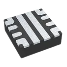
VQFN-HR, package code/drawingRPW, 10 pins - Official TI part page reports package
RPW, 10 pins, ACTIVE status.
Table
| Current terminal | Pin number | Current pin type |
|---|---|---|
| EN/UVLO_1 | 1 | Unspecified |
| 2 | Unspecified | |
| PG | 3 | Unspecified |
| ~FLT_1 | 4 | Unspecified |
| IN | 5 | Unspecified |
| OUT | 6 | Unspecified |
| DVDT_1 | 7 | Unspecified |
| GND | 8 | Unspecified |
| ILM | 9 | Unspecified |
| ITIMER_1 | 10 | Unspecified |
| EN/UVLO_2 | 11 | Unspecified |
| ~FLT_2 | 12 | Unspecified |
| DVDT_2 | 13 | Unspecified |
| ITIMER_2 | 14 | Unspecified |
Datasheet pinout expected for TPS259814ARPWR / RPW 10-pin
| Datasheet pin | Name | Recommended Flux pin type | Short description |
|---|---|---|---|
| 1 | EN/UVLO | Input | Enable / UVLO input |
| 2 | EN/OVLO | Input | Enable / OVLO input |
| 3 | PG | Output | Power-good open-drain output |
| 4 | FLT | Output | Fault open-drain output |
| 5 | IN | Power In | Power input |
| 6 | OUT | Power Out | Power output |
| 7 | DVDT | Passive | Slew-rate capacitor pin |
| 8 | GND | Ground | Ground reference |
| 9 | ILM | Passive | Current limit / monitor |
| 10 | ITIMER | Passive | Overcurrent timer capacitor |
EN/UVLO_1, ~EN~/OVLO, PG, ~FLT_1, IN, OUT, DVDT_1, GND, ILM, ITIMER_1, plus duplicated EN/UVLO_2, ~FLT_2, DVDT_2, and ITIMER_2.TPS259474LRPWR.kicad_mod, which appears to be for a different MPN family and should be treated as suspicious unless intentionally shared and verified against the TI RPW0010A package drawing.-
Pin count mismatch — critical
- Project has 14 terminals/pads.
- Official TI information for TPS259814ARPWR indicates 10 pins in RPW/VQFN-HR.
- Extra project pins: 11
EN/UVLO_2, 12~FLT_2, 13DVDT_2, 14ITIMER_2.
-
Package mismatch — critical
- Project property
Package or Case CodeisTO, which does not match officialRPW/ VQFN-HR 10-pin package.
- Project property
-
Footprint asset mismatch — critical
- Current footprint asset is named
TPS259474LRPWR.kicad_mod, notTPS259814ARPWR. - The current layout exposes 14 pads, inconsistent with the official 10-pin RPW package.
- Current footprint asset is named
-
Pin naming mismatch — moderate
- Pin 2 is shown as
~EN~/OVLO; expected datasheet naming isEN/OVLOor equivalent active-low enable/OVLO notation. - Pin 4
~FLT_1should map toFLT/ active-low fault output. The suffix_1suggests duplicated imported pins. - Pins 7 and 10 have
_1suffixes, again suggesting duplicate import artifacts.
- Pin 2 is shown as
-
Missing pin metadata — moderate
- All 14 terminals currently have
Pin Type: Unspecified. - Pin descriptions, sections, pin groups, and orientations are not populated.
- All 14 terminals currently have
-
Description typo — low
- Project description says
6-m eFuse; this should likely be6-mΩ eFuse.
- Project description says
- Replace or correct the symbol to exactly 10 terminals for TPS259814ARPWR RPW package.
- Remove or flag the extra pins 11–14 after confirmation.
- Replace/verify the footprint against TI
RPW0010A/ 10-pin VQFN-HR mechanical drawing. - Update
Package or Case CodefromTOtoRPW0010AorVQFN-HR-10 (RPW). - Update pin types and descriptions per the expected pinout table above.
- Consider updating
Designator PrefixfromICtoU, unless your library convention intentionally usesIC. - Correct the description to include
6-mΩ.


Welcome 👋
Flux accelerates your PCB design with AI.
Create your account to start using this component and bring your ideas to life.